

LDR sensor module | How LDR Sensor Works
Hello friends! Welcome back to another tutorial of ElectroDuino. This blog is based on the LDR sensor module | How LDR Sensor Works | How to make an LDR sensor module. Here we will discuss the Introduction to LDR sensor module or Photo-resistor sensor, Pin Diagram, Module Hardware Overview, Sensor module Circuit Diagram, Working Principle, its Specifications, and Applications.
Introduction
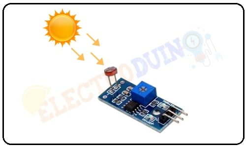
LDR sensor module is a low-cost digital sensor as well as analog sensor module, which is capable to measure and detect light intensity. This sensor also is known as the Photoresistor sensor. This sensor has an onboard LDR(Light Dependent Resistor), that helps it to detect light. This sensor module comes with 4 terminals. Where the “DO” pin is a digital output pin and the “AO” pin is an analog output pin. The output of the module goes high in the absence of light and it becomes low in the presence of light. The sensitivity of the sensor can be adjusted using the onboard potentiometer.
LDR Sensor Module or Photoresistor sensor Pin Diagram
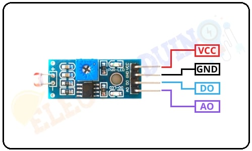
| Pin No | Pin Name | Description |
| 1 | VCC | +5 v power supply Input Pin |
| 2 | GND | Ground (-) power supply Input Pin |
| 3 | DO | Digital Output Pin |
| 4 | AO | Analog Output Pin |
| How to use LDR Sensor with Arduino: Interfacing LDR Sensor with Arduino |
LDR Sensor Module or Photoresistor sensor Hardware Overview
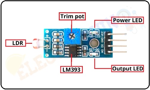
The LDR sensor module consists mainly of the LDR, LM393 Comparators, Variable Resistor (Trim pot), Power LED, output LED.
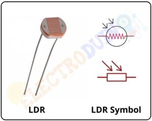
1. LDR or Light Dependent Resistor
LDR or Light Dependent Resistor is one type of variable resistor. It is also known as a photoresistor. The Light Dependent Resistor (LDR) works on the principle of “Photo Conductivity”. The LDR resistance is change according to the light intensity falls on the LDR. When light intensity increase on the LDR surface, then the LDR resistance will decrease and the element conductivity will increases. When light intensity decrease on the LDR surface, then the LDR resistance will increase and the element conductivity will decrease.
 |
 |
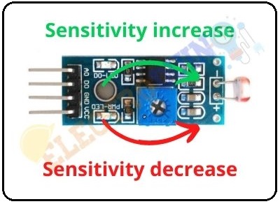
3. Variable Resistor (Trim pot)
The LDR sensor module has an onboard variable resistor or potentiometer, this variable resistor is a 10k preset. It is used to set the sensitivity of this LDR sensor. Rotate the preset knob to adjust the sensitivity of the light intensity detection. If we will rotate the preset knob in the clockwise direction, the sensitivity of the light intensity detection will increase. If it rotated counterclockwise direction, the sensitivity of the light intensity detection will decrease.
4. Power LED
This onboard LED indicates the LDR sensor module power supply is ON or OFF. When we turn on the sensor power supply this Green LED is also turn on.
5. Output LED
When the LDR sensor detects the light, the green LED is turn on. When the LDR sensor detects the darkness, the green LED is turn off.
How to make an LDR Sensor Module
Components Required
| Components Name | Quantity |
| IC: LM358 or LM393 (You can choose any one of these ICs) | 1 |
| LDR or Light Dependent Resistor (R2) | 1 |
| 1K Resistor (R1, R4) | 2 |
| 10K Resistor (R3) | 1 |
| 10K Potentiometer (VR1) | 1 |
| 0.1 uF Ceramic Capacitor (C1, C2) | 2 |
| Green LED (D1, D2) | 2 |
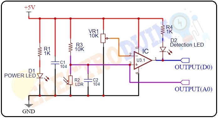
LDR Sensor Module Circuit Diagram
How IR Sensor Module Works
First of all, we need to connect the LDR sensor module to a 5v power supply. Then set the threshold voltage at the Non-Inverting input (3) of the IC according to the present light intensity by rotating the preset knob for setting the sensor sensitivity.
When light intensity increase on the surface of the LDR then the resistance of the LDR decreases. Then the maximum amount of voltage will be allocated across the resistor(R3). So, a Low amount of voltage from the LDR is given to the Inverting input (2) of the IC. Then the Comparator IC compares this voltage with the threshold voltage. In this condition, this input voltage is less than the threshold voltage, so the sensor output goes LOW (0).
In contrast, When light intensity decrease (low/dark) on the surface of the LDR then the resistance of the LDR increases. Then the maximum amount of voltage will be allocated across the LDR (R2). So, a High amount of voltage from the LDR is given to the Inverting input (2) of the IC. Then the Comparator IC compares this voltage with the threshold voltage. In this condition, this input voltage is greater than the threshold voltage, so the sensor output goes High (1).
Sensor Specifications
| Parameter | Value |
| Operating voltage | 5V or 3.3V DC |
| Comparator chip | LM393 |
| Module Pins | 3 pins |
| Output type | Digital outputs (D0) |
| Sensitivity | Adjustable |
| Indicator LED | Output and power LED indicator |
| PCB size | 3cm * 1.6cm |
| Fixed Hole Diameter | 3mm |
Application
- Detecting the darkness and light.
- Automatic light on/off system
- It is used to measure light intensity.
| How to use LDR Sensor with Arduino: Interfacing LDR Sensor with Arduino |


Supper Blog