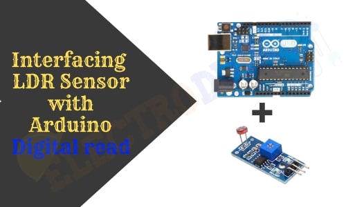
Interfacing LDR Sensor with Arduino | LDR Sensor Arduino Code for Digital Output
Hello friends! Welcome back to ElectroDuino. This tutorial is base on the Interfacing LDR Sensor module with Arduino and LDR Sensor Arduino Code for Digital Output. After understanding the “LDR sensor module | How it’s Works” in the previous blog. Here we will discuss how to use the LDR Sensor module with Arduino, Circuit diagram, Digital data read Arduino Code. Also, we will learn how to make a dark & light detector project using the LDR sensor module and Arduino.
Introduction
Interfacing the LDR Sensor module with Arduino a first step to understanding how to use an IR sensor in different projects. This basic blog tutorial helps us to understand how to connect the LDR sensor module with Arduino, how to reads output data from the sensor using Arduino programming/code, and print the output value on Serial Monitor Window of IDE. Here we will make a basic project, how to make a dark & light detector project using the LDR sensor module and Arduino.
Components Required
| Components Name | Quantity |
| Arduino UNO ((you can use other types of Arduino like Arduino NANO, MEGA, pro mini, etc) | 1 |
| LDR Sensor Module | 1 |
| Red LED | 1 |
| Green LED | 1 |
| 220ohm Resistor | 2 |
| Breadboard | 1 |
| Connecting wires | As required in the circuit diagram |
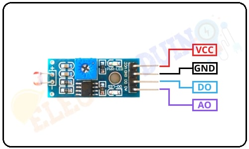
LDR Sensor Module or Photoresistor sensor Pin Diagram
How to use LDR Sensor with Arduino
First of all, we connected the Vcc pin to the Arduino 5v pin and the GND pin is connected to the Arduino ground (GND) pin. The digital output pin is connected to the Arduino digital pin to read the digital output value from the LDR sensor module.
LDR Sensor with Arduino Circuit diagram for Digital Output
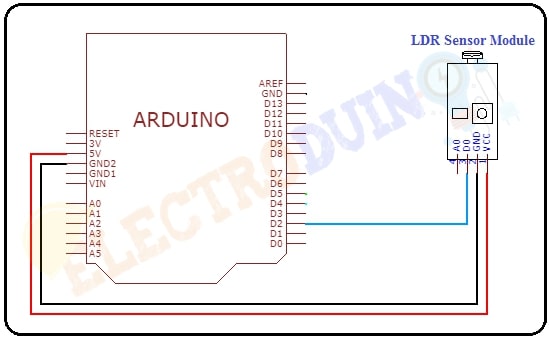
Circuit Wiring
| Components Pin | Arduino Pin |
| IR sensor Vcc Pin | + 5v Pin |
| IR sensor GND Pin | GND (ground) pin |
| IR sensor OUT Pin | Digital pin “D2” |
Arduino Code for Read Digital Output
Now we need to write a few lines of code in Arduino IDE Software. We will use the “digitalRead()” function in the Arduino program to read the sensor output. Also, we will print the sensor output data on the Serial monitor of the Arduino IDE.
/* interfacing LDR sensor with Arduino | LDR Sensor Arduino Code for Digital Output
www.electroduino.com */

// Declare your LDR sensor out pin connected Arduino pin “D3”
 int LDRSensor = 2;

void setup()
 {
  //Initialize Sensor (pin3) as an INPUT.
  pinMode (LDRSensor, INPUT);
  //Define baud rate for serial communication
  Serial.begin (9600);
 }

void loop()
 {
  //Read Digital output value from sensor using digitalRead()function
  int Sensordata = digitalRead (LDRSensor);
  //Print the sensor value on your serial monitor window
  Serial.print("Sensor value:");
  Serial.println(Sensordata);
  //Delay for 1 second to get clear output on the serial monitor
  delay(1000);
 }
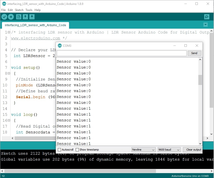
Sensor Output on Serial monitor
When the sensor detects light then the output goes LOW (0) and when the sensor detects Darkness then the output goes HIGH(1).
Dark & Light Detector
In this part, we will learn how to make a dark & light detector project using the LDR sensor module and Arduino. Here the LDR sensor used to detect light and dark. We have used 2 colors of LEDs, the Red LED is used to indicate Darkness and the green LED is used to indicate Light. This system is controlled by Arduino.
Arduino LDR Sensor Circuit diagram for Digital Output
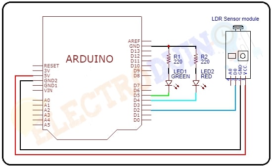
Circuit Wiring
| Components Pin | Arduino Pin |
| Sensor Vcc pin | + 5v Pin |
| Sensor GND pin | GND (ground) pin |
| LDR sensor DO (Digital Out) pin | Digital pin D2 |
| LED1 (Green) positive terminal | Digital pin D5 |
| LED1 (Green) negative terminal | GND pin through the 220ohm resistor. |
| LED2 (Red) positive terminal | Digital pin D4 |
| LED2 (Red) positive terminal | GND pin through the 220ohm resistor. |
How the LDR Sensor Works as a Dark & Light Detector
In this circuit, the Sensor digital output pin is connected to the Arduino digital pin “D2”. The LDR sensor gives logic LOW (0) as digital output when light falls on the surface of the LDR, and it will give logic HIGH (1) digital output when no light falls on the surface of the LDR.
The LED1 (Green) and LED2 (Red) are uses as indicators, where the LED1 (Green) indicates and the LED2(Red) indicates the dark.
This project works using simple Logic.
That is If Arduino reads HIGH(1) data from the sensor output pin, LED2(Red) will turn ON, and LED1(Green) will turn OFF, it means that it is dark. Else if Arduino reads LOW(0) data from the sensor output pin, LED1(Green) will turn ON, and LED2(Red) will turn OFF, It means that it is Light.
These logics will be implemented by the Arduino program.
Dark & Light Detector Arduino Code
/* Dark & Light Detector using LDR Sensor Arduino Code
www.electroduino.com */
// Declare your LDR sensor out pin connected Arduino pin “D2”
 int LDRSensor = 2;
 // Declare your Green and Red LED pin connected Arduino pin “D5 and D4”
 int LED1 = 5;
 int LED2 = 4;

void setup()
 {
  //Initialize Sensor (pin3) as an INPUT.
  pinMode (LDRSensor, INPUT);
  //Initialize LEDs as an OUTPUT
  pinMode (LED1, OUTPUT);
  pinMode (LED2, OUTPUT);
  //Define baud rate for serial communication
  Serial.begin (9600);
 }

void loop()
 {
   //Read Digital output value from sensor using digitalRead()function
   int Sensordata = digitalRead (LDRSensor);
   //Print the sensor value on your serial monitor window
   Serial.print("Sensor value:");
   Serial.println(Sensordata);
 // when LDR sensor detect light
 if (Sensordata == 0)
  {
   digitalWrite(LED1, HIGH); // Green LED turn on
   digitalWrite(LED2, LOW);  // Red LED turn off
  }

 else if (Sensordata == 1)
  {
   digitalWrite(LED1, LOW);  // Green LED turn off
   digitalWrite(LED2, HIGH); // Red LED turn on
  }
 }
Output
- When light falls on the surface of the LDR, then LED1(Green) will turn ON, and LED2(Red) will turn OFF, It means that it is Light.
- When no light falls on the surface of the LDR, then LED2(Red) will turn ON, and LED1(Green) will turn OFF, It means that it is dark.