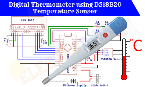
Digital Thermometer using DS18B20 Temperature Sensor
Hello friends! Welcome back to ElectroDuino. This blog is based on the Digital Thermometer using DS18B20 Temperature Sensor and Arduino. Here we will discuss Introduction to Digital Thermometer using DS18B20 Temperature Sensor, Project Concept, Block Diagram, Components Required, Circuit Diagram, Working Principle, and Arduino Code.
Introduction
Trees are performed a very important role in our life, they produce oxygen for us. Almost all of us love to plant trees in our garden, rooftop garden, and house (Indoor plants). It is not only necessary to plant trees, but also to take proper care of them, and water should be given regular basis. But in this busy life sometimes we forgot to water the plants, which damages our plants. To overcome this problem here we will be going to build an Automatic Plant watering system that automatically waters the plants without any human effort. This system continuously senses the moisture levels of the plant soil. When the soil moisture levels will decrease this device automatically water the plants. This system not only saves your time, but it also saves the waste of water. This system is also known as the Automatic Plant Irrigation System.
This project is sponsored by PCBWay.com. It’s a Professional grate PCB prototype service company. They are providing you 10 high-quality PCBs at only 5$. At first register on the website, then fill in all the specifications like Dimensions, Layers, Thickness, color, and Quantity. In the last upload your Gerber files and place your Order Now. After completing all the processes, they produce your PCB prototype within 24 hours.
So, order now to get a high-quality PCB prototype quickly from PCBWay.com

Project Concept of Digital Thermometer using DS18B20 Temperature Sensor
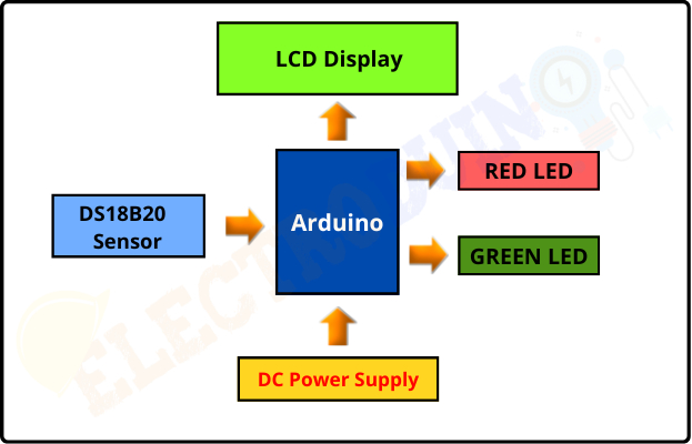
This project is not that much of complex, few components are needed to build it. The key components of this project are Arduino Nano, Soil moisture sensor, DS18B20 Temperature sensor, Relay Module, 16×2 LCD Display, LED, and Water Pump. The Arduino nano is used as the main microcontroller of this system, where it is used to control the whole system. The Soil moisture sensor is used to sense the moisture levels of the plant soil. This sensor senses the soil moisture levels and produces output. When the Arduino detected the low moisture level in the soil by the sensor, then the Arduino gives the signal to the Relay module to turn on the Pump for automatically watering the plant. When there will enough water in the soil, the Arduino again sends a signal to the relay to stop the pump. The DS18B20 Temperature Sensor is used to measure the temperature of the soil. The LCD display shows the soil moisture levels, soil temperature, and pump status (on/off). The LEDs also used to indicate the pump status.
Block Diagram of Digital Thermometer using DS18B20 Temperature Sensor
For this project you should know:
- DS18B20 Waterproof Temperature Sensor | How it’s Works
- Interfacing DS18B20 Temperature Sensor with Arduino
- 16×2 LCD Display Module | How it’s Works
Components Required
| Components Name | Quantity |
| Arduino NANO (you can use other types of Arduino like Arduino UNO, MEGA, Pro mini, etc) | 1 |
| DS18B20 Waterproof Temperature Sensor | 1 |
| 16×2 LCD Display Module | 1 |
| 220 ohm Resistor (R1, R2, R3) | 3 |
| 4.7K ohm Resistor (R4) | 1 |
| 10K ohm Potentiometer (VR1) | 1 |
| Red LED (D1) | 1 |
| Green LED (D2) | 1 |
| 9v Power Supply | 1 |
| Slide Switch | 1 |
| PCB board | 1 |
| Connecting wires | As required in the circuit diagram |
Tools Required
| Tools Name | Quantity |
| Soldering Iron | 1 |
| Soldering wire | 1 |
| Soldering flux | 1 |
| Soldering stand | 1 |
| Multimeter | 1 |
| Desoldering pump | 1 |
| Wirecutter | 1 |
Software Required
|
|
Arduino IDE (Integrated Development Environment) |

Required Library
We need to add 2 libraries in Arduino IDE software. These are:
- DallasTemperature library
- OneWire library
*Click here to learn How to Download and install the DallasTemperature library and OneWire library
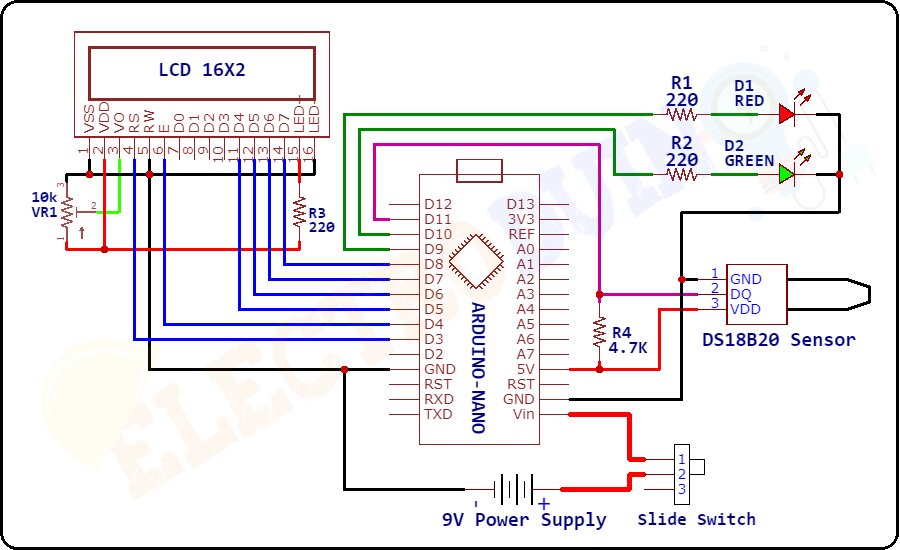
Circuit Diagram/Schematic of Digital Thermometer using DS18B20 Temperature Sensor and Arduino
Working Principle of Digital Thermometer using DS18B20 Temperature Sensor
After connecting all the components as per the circuit diagram, now our digital thermometer is ready to work. The working principle of this project is very easy. First of all, when we are powering up this project the DS18B20 Waterproof Temperature Sensor starts sensing the surrounding temperature and generates Output values from its Data pin. Then the Arduino Nano microcontroller board read these output values from the Sensor Data pin which is connected to the Digital Pin D11 of the Arduino. Using these output values the Arduino calculates the temperature values through the programming. It calculates the temperature values in Celcius (°C) and Farenhite (°F) Format. Now Arduino displays these Temperature values on a 16×2 LCD Display Module. In this project we have used two LEDs, one is Red LED, and another one is Green LED. These are mainly used for Temperature indicators. The Green LED and Red LED are connected to the Digital Pin D9 and D10 of the Arduino respectively. When the temperature values are under 50°C, this time the Arduino gives +5V (D9 = HIGH) to the Green LED to Turn ON the LED. This indicates the temperature is normal. When the temperature values cross 50°C, then the Arduino gives +5V (D10 = HIGH) to the Red LED to Turn ON the LED. This indicates the temperature is high.
Arduino Code for Digital Thermometer
/* Digital Thermometer using DS18B20 Temperature Sensor and Arduino.
More info: https://www.electroduino.com */

//Include librarie for LCD Display
#include <LiquidCrystal.h>
// Include librarie for DS18B20 Temperature Sensor
#include <OneWire.h>
#include <DallasTemperature.h>

// Define LCD display pins to the Arduino Pin
const int RS = 3, EN = 4, D4 = 5, D5 = 6, D6 = 7, D7 = 8;
LiquidCrystal lcd (RS, EN, D4, D5, D6, D7);

// Define which pin of the Arduino is connected to DS18B20 Temperature Sensor.
#define ONE_WIRE_BUS 11

// Define the Arduino pin which is connected to the Red LED
const int RED_LED_Pin = 9;
// Define the Arduino pin which is connected to the Green LED
const int GREEN_LED_Pin = 10;

// Create a new instance of the oneWire class to communicate with any OneWire device:
OneWire oneWire(ONE_WIRE_BUS);

// Pass the oneWire reference to DallasTemperature library:
DallasTemperature sensors(&oneWire);

void setup()
 {
  // Begin serial communication at a baud rate of 9600:
  Serial.begin(9600);
  // initialize LCD and set up the number of columns and rows
  lcd.begin(16, 2);

  // Start up the library:
  sensors.begin();

  // Set Arduino Pin as Output Pin
  pinMode(RED_LED_Pin, OUTPUT);
  pinMode(GREEN_LED_Pin, OUTPUT);

  // Print Beginning Message on LCD Display
  lcd.setCursor(4,0);
  lcd.print("Digital");
  lcd.setCursor(2,1);
  lcd.print("Thermometer");
  // Wait 2 second:
  delay(2000);
 }

void loop()
 {
  // Send the command for all devices on the bus to perform a temperature conversion:
  sensors.requestTemperatures();

  // Fetch the temperature in degrees Celsius for device index:
  float tempC = sensors.getTempCByIndex(0); // the index 0 refers to the first device
  // Fetch the temperature in degrees Fahrenheit for device index:
  float tempF = sensors.getTempFByIndex(0);

  // Print the temperature in Celsius in the Serial Monitor:
  Serial.print("Temperature: ");
  Serial.print(tempC);
  Serial.print((char)223); // shows degree symbol
  Serial.print("C  |  ");

  // Print the temperature in Fahrenheit
  Serial.print(tempF);
  Serial.print((char)223); // shows degree symbol
  Serial.println("F");

  lcd.clear();
  //Print the temperature in Celsius on LCD Display
  lcd.setCursor(0, 0);  // Set the Message Position at the First Row
  lcd.print("Temp: ");
  lcd.print(tempC);     // Print the Temperature in Celsius
  lcd.print((char)223); // Print ° character
  lcd.print("C");
  // Print the temperature in Fahrenheit on LCD Display
  lcd.setCursor(6, 1);  // Set the Message Position at the Second Row
  lcd.print(tempF);     // Print the Temperature in Fahrenheit
  lcd.print((char)223); // Print ° character
  lcd.print("F");
  // Wait 1 second:
  delay(1000);
  // When temperature is more than 50°C
  if (tempC > 50) // here you can change the temperature threshold value of led changes
   {
    digitalWrite (RED_LED_Pin, HIGH); // RED LED ON
    digitalWrite (GREEN_LED_Pin, LOW);// GREEN LED OFF
    }
  else
   {
    digitalWrite (RED_LED_Pin, LOW); // RED LED OFF
    digitalWrite (GREEN_LED_Pin, HIGH); // GREEN LED ON
    }
  delay(1000);

}