
Introduction to L298N Motor Driver | How it’s work
Hello friends! Welcome back to ElectroDuino. This blog is base on Introduction to L298N Motor Driver | How it’s work. Here we will discuss the Introduction to L298N Motor Driver Module, module hardware overview, pin diagram, Working Principle, Features, and applications.
Introduction
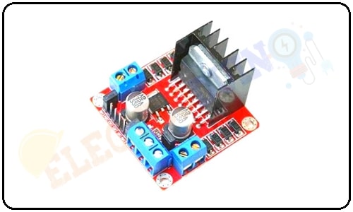
L298N module is a high voltage, high current dual full-bridge motor driver module for controlling DC motor and stepper motor. It can control both the speed and rotation direction of two DC motors. This module consists of an L298 dual-channel H-Bridge motor driver IC. This module uses two techniques for the control speed and rotation direction of the DC motors. These are PWM – For controlling the speed and H-Bridge – For controlling rotation direction. These modules can control two DC motor or one stepper motor at the same time.
L298N Motor Driver Hardware Overview
This motor driver module consists of two main key components, these are L298 motor driver IC and a 78M05 5V regulator.
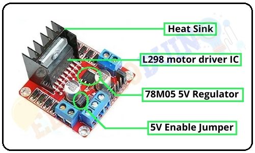
L298 motor driver IC
L298 is a high voltage, high current dual full-bridge motor driver IC. It accepts standard TTL logic levels (Control Logic) and controls inductive loads such as relays, solenoids, DC and Stepper motors. This is a 15 pin IC. According to the L298 datasheet, its operating voltage is +5 to +46V, and the maximum current allowed to draw through each output 3A. This IC has two enable inputs, these are provided to enable or disable the device independently of the input signals.
A black color heat sink is attached to the L298 IC of the module. A heat sink is a passive heat exchanger that transfers the heat generated by an electronic or a mechanical device to a fluid medium, often air or a liquid coolant.
78M05 5V Regulator
The module has an on-board 78M05 5V Voltage regulator. This Voltage regulator will be performed only when the 5V Enable jumper is placed. When the power supply is less than or equal to 12V, then the internal circuitry will be powered by the voltage regulator, and the 5V pin can be used as an output pin to power the microcontroller or other circuitry (sensor).
The jumper should not be placed when the power supply is greater than 12V and separate 5V should be given through 5V terminal to power the internal circuitry.
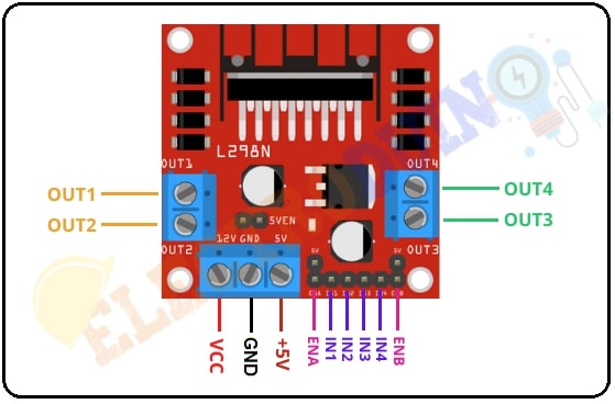
L298N Motor Driver Module Pin Diagram
|
Pin No. |
Pin Name |
Description |
|
Power Supply Pins |
||
| 1 | VCC | VCC pin is used to supply power to the motor. Its input voltage is between 5 to 35V. |
| 2 | GND | GND is a ground pin. It needs to be connected to the power supply ground(negative). |
| 3 | +5V | +5V pin supplies power for the switching logic circuitry inside the L298N IC. If the 5V-EN jumper is in place, this pin acts as output and can be used to power up a microcontroller or other circuitry (sensor). If the 5V-EN jumper is removed, you need to connect it to the 5V power supply of the microcontroller. |
|
Control Pins |
||
| 1 | IN1 | These pins are input pins of Motor A. These are used to control the rotating direction of Motor A. When one of them is HIGH and the other is LOW, Motor A will start rotating in a particular direction. If both the inputs are either HIGH or LOW the Motor A will stop. |
| 2 | IN2 | |
| 3 | IN3 | These pins are input pins of Motor B. These are used to control the rotating direction of Motor A. When one of them is HIGH and the other is LOW, Motor A will start rotating in a particular direction. If both the inputs are either HIGH or LOW the Motor A will stop. |
| 4 | IN4 | |
|
Speed Control Pins |
||
| 1 | ENA |
ENA pin is used to control the speed of Motor A. If a jumper is present on this pin, so the pin connected to +5 V and the motor will be enabled, then the Motor A rotates maximum speed. if we remove the jumper, we need to connect this pin to a PWM input of the microcontroller. In that way, we can control the speed of Motor A. If we connect this pin to Ground the Motor A will be disabled. |
| 2 | ENB |
ENB pin is used to control the speed of Motor B. If a jumper is present on this pin, so the pin connected to +5 V and the motor will be enabled, then the Motor B rotates maximum speed. if we remove the jumper, we need to connect this pin to a PWM input of the microcontroller. In that way, we can control the speed of Motor B. If we connect this pin to Ground the Motor B will be disabled. |
|
Output Pins |
||
| 1 | OUT1 & OUT2 | This terminal block will provide the output for Motor A. |
| 2 | OUT3 & OUT4 | This terminal block will provide the output for Motor B. |
How Motor Driver Module Works
This module uses two techniques for the control speed and rotation direction of the DC motors. These are H-Bridge – For controlling rotation direction and PWM – For controlling the speed.
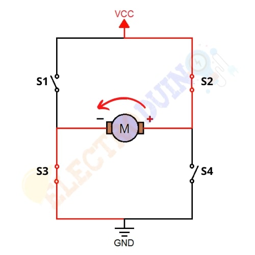
H-Bridge Techniques
L298n motor driver module uses the H-Bridge technique to control the direction of rotation of a DC motor. In this technique, H-Bridge controlled DC motor rotating direction by changing the polarity of its input voltage.
An H-Bridge circuit contains four switching elements, like transistors (BJT or MOSFET), with the motor at the center forming an H-like configuration. Input IN1, IN2, IN3, and IN4 pins actually control the switches of the H-Bridge circuit inside L298N IC.
We can change the direction of the current flow by activating two particular switches at the same time, this way we can change the rotation direction of the motor.
Case 1
When S1, S2, S3, and S4 all switches are open then no current goes to the Motor terminals. So, in this condition, the motor is stopped (not working).

Case 2
When the switch S1 and S4 are closed, then the motor left terminal is getting a positive (+) voltage and the motor right terminal is getting a negative(-) voltage. So, in this condition motor start rotating in a particular direction (clockwise).

Case 3
When S2 and S3 switches are closed, then the right motor terminal is getting a positive (+) voltage and the left motor terminal is getting a negative (-) voltage. So, in this condition motor start rotating in a particular direction (anticlockwise).
PWM (Pulse Width Modulation) Techniques
L298n motor driver module uses the PWM technique to control the speed of rotation of a DC motor. In this technique, the speed of a DC motor can be controlled by changing its input voltage.
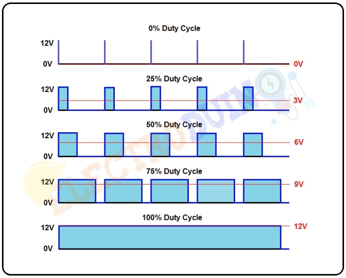
Pulse Width Modulation is a technique where the average value of the input voltage is adjusted by sending a series of ON-OFF pulses. The average voltage is proportional to the width of the pulses, these pulses known as Duty Cycle.
If the duty cycle higher, then the average voltage is applied to the DC motor (High Speed), and the lower the duty cycle, the less the average voltage being applied to the dc motor(Low Speed).
Module Specifications & Features
|
Parameter |
Value |
| Operating Voltage | 5V – 46V |
| Operating Current | 2A |
| Logic Voltage | 5V |
| Logical Current | 0-36mA |
| Maximum Power (W) | 25W |
| Driver Chip | L298 dual-channel H-Bridge motor driver IC |
| LED lights indicators | Power-On LED indicator |
| Drives motor | Drives up to 4 motors (2 for each motor output terminal block) or One Stepper Motor |
| Module Dimensions | 44 x 44 x 28 (LxWxH)mm |
Applications
- Control DC motors.
- Control stepping motors
- In Robotics


