

LM393 Comparator IC – Pinout, Specifications & Working Principle
Hello friends! Welcome back to ElectroDuino. This blog is base on the LM393 comparator IC. Here we will discuss the Introduction to LM393 comparator IC, IC pin diagram, Working Principle, Features, LM393 IC Equivalent IC, and it’s applications.
Introduction
The LM393 integrated circuit (IC) is a dual differential comparator, it consists of two inbuilt operational amplifiers. Each comparator accepts 2 inputs for comparison. The comparator compares these two input voltages and measure which input voltage is the larger, then it provides output. These ICs can perform different tasks using a single power supply. Also, it can be work perfectly by the split power supply sources.
LM393 Comparator IC Internal Structure
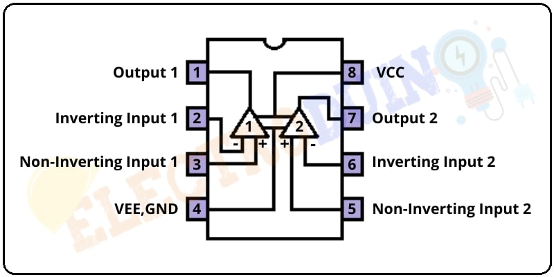
The LM393 comparator IC consists of two inbuilt operational amplifiers(Op-Amp).
The Op-Amp 1 & Op-Amp 2 negative inputs are connected to IC pin 4 and positive inputs are connected to IC pin 8.
The Op-Amp 1 Inverting input is connected to IC pin 2 and the Non-Inverting input is connected to IC pin 3. The output of the Op-Amp 1 is connected to IC pin 1.
The Op-Amp 2 Inverting input is connected to IC pin 6 and the Non-Inverting input is connected to IC pin 5. The output of the Op-Amp 1 is connected to IC pin 7.
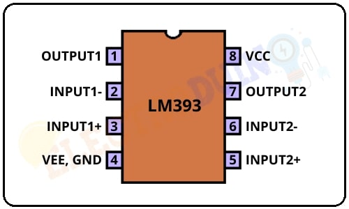
LM393 IC Pin Configuration
| Pin Number | Pin Name | Description |
| 1 | OUTPUT1 | This is the output pin of the Op-Amp 1 |
| 2 | INPUT1- | Inverting Input pin of Op-Amp 1 |
| 3 | INPUT1+ | Non-Inverting Input pin of Op-Amp 1 |
| 4 | VEE, GND | This is the Ground pin of the IC. it needs to connect to the Negative(-) terminal of Supply Voltage. |
| 5 | INPUT2+ | Non-Inverting Input pin of Op-Amp 2 |
| 6 | INPUT2- | Inverting Input pin of Op-Amp 2 |
| 7 | OUTPUT2 | This is the output pin of the Op-Amp 2 |
| 8 | VCC | This is the positive pin of the IC. it needs to connect to the Positive(+) terminal of Supply Voltage. |
Working Principle
First of all, we need to connect the power source with the Vcc and GND pin of the LM393 IC to activate the IC. Then, we need to provide two input voltage to the Op-Amp for comparison. Now, we can get an output from the Op-Amp.
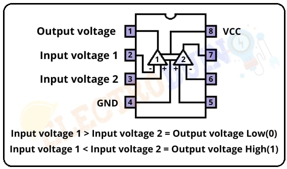
As an example, here we used the Op-Amp1 of the LM393 IC to get output. First of all, we provide input voltage 1 to the Inverting terminal (Pin2) and input voltage 2 to the Non-Inverting Terminal (Pin3).
If the input voltage 1 is greater than the input voltage 2, then the output of the op-amp will be drawn down to the ground, which means the output voltage is Low (GND).
If the input voltage 1 is less than the input voltage 2, then the output of the op-amp stays at VCC, which means the output voltage is High (VCC).
Features of LM393 IC
| Parameter | Value |
| Single voltage supply | 2V to 36V DC |
| Split supply | ±1V to ±18V |
| Drain Current | 0.4mA |
| Input Offset Voltage | Maximum ±5mV |
| Power Dissipation | 660mW |
| Package | DIP & SOIC 8 Pin |
LM393 IC Equivalents IC
LM358, TL082, LM311
Applications
- Voltage Comparator circuits.
- It’s Can be used to drive Relay, Lamp, Motor Etc.
- Zero-Crossing detector.
- Battery-Powered Applications.
- High Voltage protection/Warning.
- Oscillator circuits.


Well I really liked reading it. This tip offered by you is very constructive for good planning. Cilka Earvin Zaneta