Sound Sensor Module | How its work?
Hello friends! Welcome back to ElectroDuino. This blog is base on Sound Detection Sensor Module | How it Works. Here we will discuss the Introduction to Sound Sensor Module, pin diagram, Working Principle, Features, and applications.
Introduction
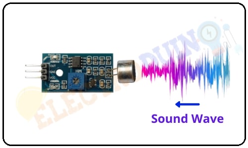
The sound sensor module is a low-cost electronic sensor that can easily detect sound. It is generally used for detecting sound intensity. This sensor has a microphone for detecting sound intensity. The electret microphone detects the sound wave and then sends it to the sensor circuit board which consists of a voltage comparator IC LM393 and potentiometer. Comparator IC LM393 process this signal and convert it into a Digital Output. The potentiometer is used to adjust the sensitivity of the sensor.
Sound Sensor Module Pin Diagram

| Pin Number | Pin Name | Description |
| 1 | VCC | +5 v power supply |
| 2 | GND | Ground (-) power supply |
| 3 | OUT | Digital Output (0 or 1) |
Sound Sensor Hardware Overview
The sound Sensor module is consists of some key components. These are Electret Microphone, LM393 Comparators, Variable Resistor (Trimpot), Power LED, output LED.
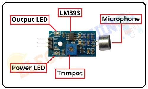
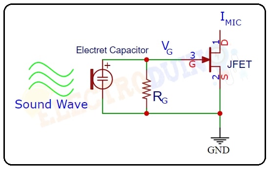
1.Electret Microphone
An electret microphone is a type of electrostatic capacitor-based electronics component, which can be receiving sound waves and transforming it into tiny electrical pulses. An electret microphone mainly consists of an Electret Capacitor, a JFET, and a resistor. The sound waves mainly receive by the Electret Capacitor. Electret Capacitor is a variable capacitor when the sound wave comes on it, then the capacitance will vary in the capacitor. It has two terminals one is Negative and another one is Positive. It is able to receive sound vibrations from across all angles.
2. Variable Resistor (Trimmer)
This sensor has an onboard variable resistor(Trimpot) or potentiometer. This variable resistor is a 10k preset. It is used to set the sensitivity of the sensor. Rotate the Trimmer knob to adjust the sensitivity of sound signal detection. If the preset knob rotated counterclockwise, then the sensor sensitivity will be increased. If it rotated clockwise, then the sensitivity will be decreased.

3. Power LED
This onboard LED indicates the Sensor power supply is ON or OFF. When we turn on the power supply this Green LED is also turn on.
4. Output LED
When the sensor detects the sound, the Green LED is turn ON. When it does not detect any sound, the Green LED is turn OFF.
How Sound Sensor Module Works
At first, we need to connect the module to the 5v power supply. Then set the threshold voltage at the Non-Inverting input (3) of the IC according to the silent environment by rotating the preset knob for setting the sensor sensitivity.
When the sensor detects Sound then a Low amount of voltage from the microphone is given to the Inverting input (2) of the IC. Then the Comparator IC compares this voltage with the threshold voltage. In this condition, this input voltage is less than the threshold voltage, so the sensor output goes LOW (0).
In contrast, when the sensor does not detect Sound then a High amount of voltage from the microphone is given to the Inverting input (2) of the IC. Then the Comparator IC compares this voltage with the threshold voltage. In this condition, this input voltage is greater than the threshold voltage, so the sensor output goes High (1).
Sensor Specifications
| Parameter | Value |
| Operating Voltage | 3.3V – 5V |
| Operating Current | 15 mA |
| Comparator chip | LM393 |
| Sensor type | Microphone |
| Sensitivity | Adjustable via Trimmer |
| Output type | Digital Output (0 or 1) |
| LED lights indicators | Power (red) and Output (red) |
| PCB Size | 3.2cm x 1.4cm |
Application
- It is mainly used to detect sound