IR Infrared Flame Sensor Module | How Fire Sensor Works
Hello friends! Welcome back to ElectroDuino. This blog is base on IR Infrared Flame Sensor Module | How it Works | How to make an IR Infrared Flame Sensor Module. Here we will discuss the Introduction to IR Infrared Flame Sensor Module, Pin Diagram, Hardware Overview, Circuit Diagram, Working Principle, its Specifications, and Applications.
Introduction
A Flame Sensor module or Fire Sensor module is a small size electronics device that can detect a fire source or any other bright light sources. This sensor basically detects IR (Infrared) light wavelength between 760 nm – 1100 nm that is emitted from the fire flame or light source. The flame sensor comes with a YG1006 Phototransistor sensor which is a high speed and high sensitivity. Two types of IR Infrared Flame Sensor Module available in the market one having three pins (D0, Gnd, Vcc) and another one having four pins (A0, D0, Gnd, Vcc) both are can be easily used with Arduino and other microcontroller boards.
Difference between 3 pins and 4 pin Flame Sensor Module
Two types of flame sensors available in the market both types are consist of the same components. Also, the parameters of both sensors like Operating Voltage, Current Comparator chip, Sensor type, Spectrum range, Detection angle, and Detection range everything is similar.
But, these modules have a major difference, that is one module is consists of 3 pins(D0, Gnd, Vcc), and it’s can able to provides only Digital Output. Another module is consists of 4 pins((A0, D0, Gnd, Vcc) and it’s can able to provide Digital Output and Analog Output.
IR Infrared Flame Module Pin Diagram
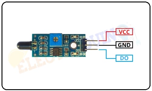
3 pins Flame Sensor Module
|
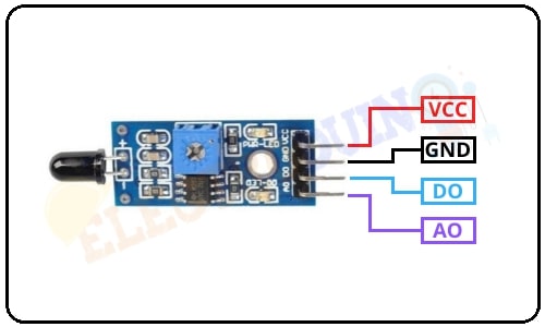
4 pin Flame Sensor Module
|
IR Infrared Flame Sensor Module Hardware Overview
4 pin and 3 pin sensors are consist of the same components. The key components of these sensors are YG1006 NPN Phototransistor, LM393 Comparators IC, Variable Resistor (Trim pot), Power LED, Output LED.

1.YG1006 Phototransistor
YG1006 Phototransistor is a 5mm NPN Transistor. The Phototransistor is coated by black epoxy, which makes it sensitive to infrared radiation. But, it looks like a two-terminal block LED from the outside. It is used to sense flame or light in a range of 760 nm – 1100 nm wavelength. This sensor is consists of two terminals, where the long terminal is the Emitter and the shorter terminal is the collector. It has no base terminal like other transistors, when it detects light then the current starts to flow between emitter and collector.

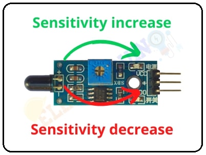
2. Variable Resistor (Trim pot)
This sensor has an onboard variable resistor (potentiometer), this is a 10k preset. Rotate the preset knob to adjust the sensitivity of fire detection. If the preset knob rotated clockwise, the sensitivity of the Flame sensor will be increased. If it rotated counterclockwise, the sensitivity of the Flame sensor will be decreased.
3. Power LED
This onboard LED indicates the flame sensor’s power supply is ON or OFF. When we will connect the power supply to the flame sensor, this LED is also turn on.
4. Output LED
When the sensor detects the fire, the Red LED is turn on. When it does not detect any fire or flame source, the Red LED is turn off.
How to Make IR Infrared Flame Sensor Module
Components Required
| Components Name | Quantity |
| IC: LM358 or LM393 (You can choose any one of these ICs) | 1 |
| YG1006 Phototransistor | 1 |
| 1K Resistor (R1, R3) | 2 |
| 10K Resistor (R2) | 1 |
| 10K Potentiometer (VR1) | 1 |
| 0.1 uF Ceramic Capacitor (C1, C2) | 2 |
| RED LED (D1, D2) | 2 |
IR Infrared Flame Sensor Module Circuit Diagram
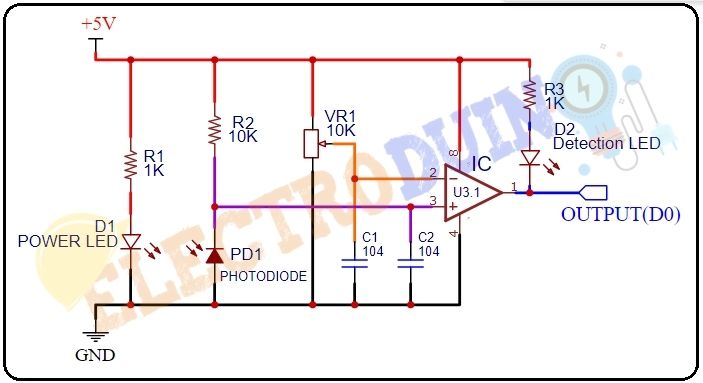
How IR Infrared Flame Sensor Module Works
At first, we need to connect the Sensor to the 5v power supply. Then set the threshold voltage at the Non-Inverting input (3) of the IC according to the absence of flame/fire by rotating the preset knob for setting the sensor sensitivity.
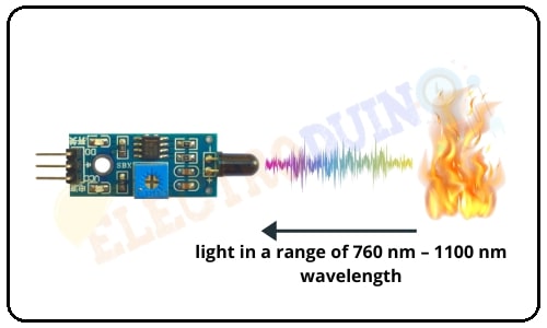
When this sensor detects fire/flame (light in a range of 760 nm – 1100 nm wavelength) then the resistance of the Phototransistor decreases. Then the maximum amount of voltage will be allocated across the Resistor(R2). So, a Low amount of voltage from the Phototransistor is given to the Inverting input (2) of the IC. Then the Comparator IC compares this voltage with the threshold voltage. In this condition, this input voltage is less than the threshold voltage, so the sensor output goes LOW (0).
In contrast, when the Flame Sensor module does not detect fire/flame (light in a range of 760 nm – 1100 nm wavelength) then the resistance of the Phototransistor is High. Then the maximum amount of voltage will be allocated across the Phototransistor. So, a High amount of voltage from the Phototransistor is given to the Inverting input (2) of the IC. Then the Comparator IC compares this voltage with the threshold voltage. In this condition, this input voltage is greater than the threshold voltage, so the sensor output goes High (1).
Sensor Specifications
| Parameter | Value |
| Operating Voltage | 3.3V – 5V |
| Operating Current | 15 mA |
| Comparator chip | LM393 |
| Sensor type | YG1006 Photo Transistor |
| Sensitivity | Adjustable via potentiometer |
| Output type | Digital output / Digital and Analog output |
| LED lights indicators | Power (red) and Output (green) |
| Spectrum range | 760nm ~ 1100nm |
| Detection angle | 0 – 60 degree |
| Operating temperature | -25℃ ~ 85℃ |
| PCB Size | 3cm X 1.6cm |
Application
- Fire detection
- Use in Fire fighting robot
- Fire alarm