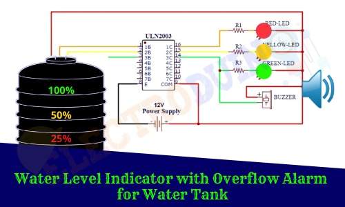
Water Level Indicator with Overflow Alarm for Water Tank
Hello friends! Welcome back to ElectroDuino. This blog is based on Water/liquid Level Indicator/monitoring system with Overflow Alarm for Water Tank using ULM2003 IC. Here we will discuss Introduction to Water Level Indicator, Project Concept, Block Diagram, Components Required, Circuit Diagram, and Working Principle.
Introduction
Day to day the drinking water crisis is increasing all over the world. It might very soon become a big problem. Therefore, it is very important for all of us to conserve water. In this modern-day, every house, building, office, and industry are using overhead water tanks, that fulfill they are daily using water demands. The groundwater is used to fill these tanks. But most of the time, we forget to turn off the Pump after water filling in the tank, which makes an overflow of water from the tankers. The overflow is a common problem for all of us that wastage lots of water. In this project tutorial, we will make a simple electronic circuit called ‘Water Level Indicator’ to solve this problem.
What is a Water/Liquid Level Indicator?
The water/liquid level indicator is a system that continuously monitors the water/liquid level in a reservoir, tank, or any other container, and gives us the correct information about the water/liquid level. It is used to overcome the overflow of water/liquid from the tankers.
Project Concept of Water/Liquid Level Indicator with Overflow Alarm
We know that water conducts electricity, the Water level indicator works upon this fact. So water can be used as a medium to open or close a circuit. This system can be used for any non-flammable liquids reservoir, tank, or other containers.
The key components of this project are ULN2003 IC, four Metal Contacts, LEDs, and Buzzer. ULN2003 is a high voltage Darling-ton array IC, it is suitable for switching inductive loads. This IC has 16 pins, where has 7 input Pins (Pin 1-7), 7 output Pins (Pin 10-16). When high input voltage (+VCC) is applied to an input pin of the IC, then the respective output pin becomes Low (ground).
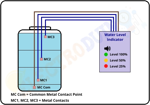
The four Metal Contacts are placed in different hight inside the water tank, as shown in the below figure. One of the Metal Contacts is connected to the positive terminal supply voltage (+Vcc), which is works as a Common Contact Point for other Metal Contacts and it is placed at the downsides of the tank. And the other 3 Metal Contacts are connected to the 3 input pins of the IC. This system is indicated three levels of water stored in the tank: 25% – low but not empty, 50% – half, and 100% – full but not overflowing.
When the water level increase in the tank, then one by one these 3 Metal Contacts will create contact with the common Contact point through the water. In this way, the input pins of the IC get high input voltage and the respective output pins of the IC become LOW (ground), which turns on the LEDs. The LEDs are used as an indicator that indicates the water level inside the tank. Here we will use 3 LEDs for indicates three different levels. The buzzer is used for alarm, when the tank becomes full it generates a loud sound that tells us to turn off the pump.
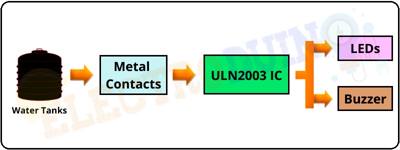
Block Diagram
Components Required
| Components Name | Quantity |
| ULN2003 IC | 1 |
| LED (Red, Yellow, Green) | 3 (one each color LED) |
| Buzzer | 1 |
| 330 ohm Resistor | 3 |
| Metal Contacts (like metal nuts or bolts) |
4 |
| 12V power supply | 1 |
| PCB board or Breadboard | 1 |
| Connecting wires | As required in the circuit diagram |
Tools Required
| Tools Name | Quantity |
| Soldering Iron | 1 |
| Soldering wire | 1 |
| Soldering flux | 1 |
| Soldering stand | 1 |
| Multimeter | 1 |
| Desoldering pump | 1 |
| Wirecutter | 1 |
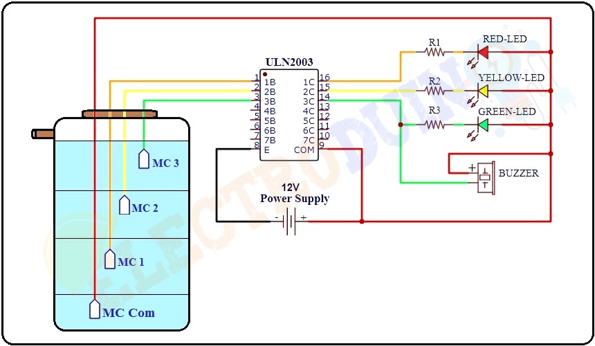
Circuit Diagram of Water Level Indicator with Overflow Alarm

Working Principle of Water Level Indicator with Overflow Alarm
After assembling all the components according to the circuit diagram place the metal contacts inside the tank properly, as shown below figure.

When the water level reaches point MC1 (Metal Contacts 1), a conductive path is created between the Common Contact Point (MC Com) and MC1 (Metal Contacts 1) by the water. It means that the positive terminal of the Power Supply connects to the input pin 1 of the ULN 2003 IC. As a result, the output pin 1 (IC pin 16) becomes Low (Ground) and the Red LED starts glowing. This indicates that the water level in the tank is about 25% (the tank is near to empty) and we need to be turned ON the pump.
When the water level reaches point MC2 (Metal Contacts 2), a conductive path is created between the Common Contact Point (MC Com) and MC2 (Metal Contacts 2) by the water. It means that the positive terminal of the Power Supply connects to the input pin 2 (IC pin 2) of the ULN 2003 IC. As a result, the output pin 3 (IC pin 15) becomes Low (Ground) and the Yellow LED also starts glowing. This indicates that the water level in the tank is about 50% (tank is half).
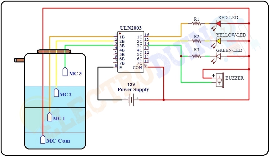
Similarly, when the water level reaches point MC3 (Metal Contacts 3), again a conductive path is created between the Common Contact Point (MC Com) and MC3 (Metal Contacts 3) by the water. Now the positive terminal of the Power Supply connects to the input pin 3 (IC pin 3) of the ULN 2003 IC. As a result, the output pin 3 (IC pin 14) becomes Low (Ground) and the Green LED also starts glowing as well as the buzzer starts ringing. This indicates that the tank is full (100%), now we need to be turned OFF the pump.