
Smart Street Light System using IR Sensor and Arduino
Hello friends! Welcome back to ElectroDuino. This blog is based on Smart Street Light System using IR Sensor, LDR, and Arduino. Here we will discuss Introduction to Smart Street Light System, Project Concept, Block Diagram, Components Required, Circuit Diagram, Working Principle, and Arduino code.
Introduction
Street lights are an essential part of all cities and the highways, that’s helpful to prevent accidents and unwanted thefts or robbery. Thousands of Street lights are installed beside the highways and the main roads. But the main problem is these street lights consume about 25-30% of the total energy spent in the city.
In this project, our main aim is to develop a “Smart Street light system” that will reduce electric power consumption. The normal street lights always glow with high intensity, who consumes high electricity. But in the case of a smart street lights system, it will glow with high intensity if there are vehicles or human movement on the road otherwise the lights will remain dim. Another advantage of this system is, street lights will automatically turn on in the evening, and turn on automatically at day time (presence of sunlight). By using this system we can save enough amount of electricity and off-course money, this saved electricity can be used to lighten few more homes in the rural areas.
Project Concept
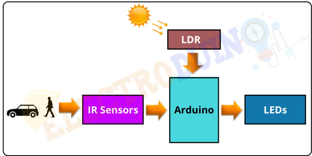
This system is very easy to implement, the key components of this project are the LDR, IR Sensor, Arduino Board, and LED. The Arduino board is the brain of this project, which controls the whole system. The IR sensor work as the eye of this project that detects the presence of vehicles or human on the road, and LDR sense the presence or absence of sunlight, and LEDs represent the street lights.
In the daytime, the system detects the sunlight by the LDR and it will be turned OFF the street lights (LED). When the system detects dark (after evening), then it will turn on the street lights (LED). After turn on the streetlight, if the system doesn’t detect any vehicles or human movement on the road by the IR Sensor, then it will glow the lights with low intensity. When the system detects vehicles or human movement by the IR Sensor, then it will glow the street lights with high intensity.
Block Diagram of Smart Street Light System
Components Required
| Components Name | Quantity |
| Arduino Nano or Arduino Uno | 1 |
| USB Cable for Arduino | 1 |
| IR Sensor | 4 |
| LDR | 1 |
| LED | 5 |
| 10K Resistor | 1 |
| 9V power supply | 1 |
| PCB board or Breadboard | 1 |
| Connecting wires | As required in the circuit diagram |
Tools Required
| Tools Name | Quantity |
| Soldering Iron | 1 |
| Soldering wire | 1 |
| Soldering flux | 1 |
| Soldering stand | 1 |
| Multimeter | 1 |
| Desoldering pump | 1 |
| Wirecutter | 1 |
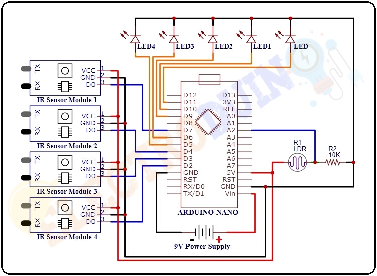
Circuit Diagram of Smart Street Light System
Working Principle
An LDR is connected to the analog pin of the Arduino. It controls the LEDs by detecting the presence or absence of sunlight.
When sufficient sunlight is present in the surroundings, then the LDR offers high resistance and acts as an insulator. In this case, the Arduino read high analog output values from the LDR and automatically turn off all LEDs (streetlights).
During the absence of sunlight, the LDR detects dark and offers Low resistance, and acts as a conductor. In this case, the Arduino read Low analog input values from the LDR and automatically turn on the LEDs (streetlights). At the same time, the IR sensor also starting its operations and start detecting any vehicles or people moving on the road.
In this project, we are using 4 IR sensors that are connected to the digital pins of the Arduino. We also use 5 LEDs that represent the streetlights, each LED connected to the PWM pins of the Arduino. Each IR sensor controls 2 LEDs.
When any of the IR sensors sense the position of the vehicle or human, its output goes LOW (0). Then the Arduino read Low output value from that sensor and increase the light intensity of two LEDs by using Pulse Width Modulation (PWM) technique.
When the IR sensors don’t detect any vehicle or human position, its output goes High (1). Then the Arduino read High output value from that sensor. Now the Arduino decreases the light intensity of the LEDs by using Pulse Width Modulation (PWM) technique.
Arduino Code
/* Smart Street Light System
   using IR Sensor, LDR and Arduino
   www.Electroduino.com */
// LED positive pin connected to Digital pins
int led = 11;
int led1 = 10;
int led2 = 9;
int led3 = 6;
int led4 = 5;
int ldr = A2; // LDR pin connected to Analog pin "A2"
int x1, x2, x3, x4,x5;

void setup()
{
 Serial.begin (9600);
 // initialize LED pins as an output
 pinMode (led,OUTPUT);
 pinMode (led1,OUTPUT);
 pinMode (led2,OUTPUT);
 pinMode (led3,OUTPUT);
 pinMode (led4,OUTPUT);
 // initialize LED Pin as an input
 pinMode (ldr,INPUT);
}
void loop()
{
 int ldrStatus = analogRead (ldr); // Read LDR output value
 Serial.println (ldrStatus);
 delay(1);
 if (ldrStatus <=100)
  {
// IR  Sensor 1 CODE
//*******************
   if (digitalRead(2)== 0) // Read IR Senso 1 value
    {
     x1=0;
     x2=1;
     digitalWrite(led,HIGH);
     digitalWrite(led1,HIGH);
     delay(100);// micro second
    }
   else
    {
     if(x1==0)
      {
       digitalWrite(led,HIGH);
       analogWrite(led,255/6);
       delay(50);
      }
     if(x2==1)
      {
       digitalWrite(led1,HIGH);
       analogWrite(led1,255/6);
       delay(50);
      }
    }
// IR  Sensor 2 CODE
//*******************
   if (digitalRead(4)== 0) // Read IR Senso 2 value
    {
     x2=0;
     x3=1;
     digitalWrite(led1,HIGH);
     digitalWrite(led2,HIGH);
     delay(100);// micro second
    }
   else
    {
     if(x2==0)
      {
       digitalWrite(led1,HIGH);
       analogWrite(led1,255/6);
       delay(50);
      }
     if(x3==1)
      {
       digitalWrite(led2,HIGH);
       analogWrite(led2,255/6);
       delay(50);
      }
    }
 // IR  Sensor 3 CODE
//*******************
   if (digitalRead(7)== 0)// Read IR Senso 3 value
    {
     x3=0;
     x4=1;
     digitalWrite(led2,HIGH);
     digitalWrite(led3,HIGH);
     delay(100);// micro second
    }
   else
    {
     if(x3==0)
      {
       digitalWrite(led2,HIGH);
       analogWrite(led2,255/6);
       delay(50);
      }
     if(x4==1)
      {
       digitalWrite(led3,HIGH);
       analogWrite(led3,255/6);
       delay(50);
      }
    }
 // IR  Sensor 4 CODE
//*******************
   if (digitalRead(8)== 0) // Read IR Senso 4 value
    {
     x4=0;
     x5=1;
     digitalWrite(led3,HIGH);
     digitalWrite(led4,HIGH);
     delay(100);// micro second
    }
   else
    {
     if(x4==0)
      {
       digitalWrite(led3,HIGH);
       analogWrite(led3,255/6);
       delay(50);
      }
     if(x5==1)
      {
       digitalWrite(led4,HIGH);
       analogWrite(led4,255/6);
       delay(50);
      }
     }
  }
 else
 {
  digitalWrite(led, LOW);
  digitalWrite(led1, LOW);
  digitalWrite(led2, LOW);
  digitalWrite(led3, LOW);
  digitalWrite(led4, LOW);
  }
 }


