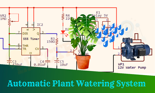
Automatic Plant Watering System using 555 Timer IC
Hello friends! Welcome back to ElectroDuino. This blog is based on How to Make Automatic Plant Watering System using 555 Timer IC. Here we will discuss the Introduction to the Automatic Plant Watering System using 555 Timer IC, Project Concept, Block Diagram, Components Required, Circuit Diagram, and Working Principle.
Introduction
Gardening is a popular hobby, and many of us love to plant different types of plants in our gardens or living space. These plants are increasing the beauty of that places as well as they also increase the surrounding oxygen level and make healthy weather. These plants are needed proper maintenance and watering on a regular basis to grow up properly. In order to take care of the plans the most essential thing is we have to water the plants whenever the soil moisture levels will decrease. But in this busy life, we don’t have time or we forget to water our plants which get harm of our plants and they become weak or die.
So, to resolve this problem in this project tutorial we will be going to be learned how to build a low-cost DIY Automatic Plant Watering System using 555 Timer IC. This system continuously checks the soil moisture levels and automatically waters our plants without any human interference. It relieves us from watering our plants daily.
Project Concept
The Automatic plant watering system project is implemented based on a very simple concept and it is easy to understand. The project concept is when the soil moisture levels go down under a specific level, then this circuit will detect the low moisture levels and turns on the water Pump automatically to water the plants. When the soil will containing sufficient water then this circuit detects High moisture levels and turn off the water pump to stop the watering on the plants.
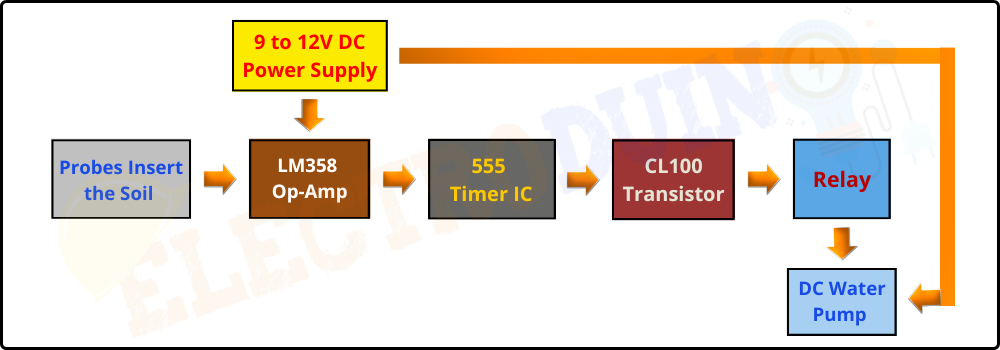
The key components of this project are Soil Moisture Probes, LM358 Op-Amp IC, 555 Timer IC, CL100 Transistor, Relay, and water pump. Basically, the probes are inserted into the soil, which detects the moisture level in the soil by measuring soil resistance. When the soil is dry the problem gets high resistance and in moist soil, it gets low resistance. According to the soil moisture levels, the probes send different Voltage (High/Low) to the LM358 Op-Amp IC. The LM358 IC analysis this voltage and generate output voltage (High/Low) and this output is given to 555 Timer IC as input. The 555 Time IC operates by this output voltage. Here we are using 555 Timer IC to set the operating time of the water pump, which means the water pump is activated for how much time after sufficient water is in the soil. The output of the timer IC is given to the CL100 transistor. Here the CL100 transistor act as a switching device that is activated by the output of the timer IC. The transistor is used to control the Relay operations (activated/deactivate) and the relay controls the water pump(on/off).
Block Diagram of Automatic Plant Watering System using 555 Timer IC
Components Required
| Components Name | Quantity |
| LM358 Op-Amp IC (IC1) | 1 |
| 555 Timer IC (IC2) | 1 |
| CL100 Transistor (Q1) |
1 |
| 10 KΩ Resistor (R1) | 1 |
| 220Ω Resistor (R2, R4) | 2 |
| 150Ω Resistor (R3) |
1 |
| 0.1µF Ceramic Capacitor (C1, C2) | 2 |
| 470 µF, 16V Electrolytic Capacitor (C3) | 1 |
| 0.01µF Ceramic Capacitor (C4) |
1 |
| 10uf/16v Electrolytic Capacitor (C5) | 1 |
| 10KΩ Potentiometer/Pot (VR1) | 1 |
| 1MΩ Potentiometer/Pot (VR2) | 1 |
| Green and Red LED (D1, D2) | 1,1 |
| 1N4007 Diode (D3) | 1 |
| 5V Relay | 1 |
| Soil Moisture Sensor Probe | 1 |
| 12V Water Pump |
1 |
| 12V 1A Power Supply Adapter | 1 |
| PCB board | 1 |
| Connecting wires | As required in the circuit diagram |
Tools Required
| Tools Name | Quantity |
| Soldering Iron | 1 |
| Soldering wire | 1 |
| Soldering flux | 1 |
| Soldering stand | 1 |
| Multimeter | 1 |
| Desoldering pump | 1 |
| Wirecutter | 1 |
Circuit Diagram/ Schematics Automatic Plant Watering System using 555 Timer IC

Working Principle of Automatic Plant Watering System using 555 Timer IC
After connecting all the components according to the circuit diagram, now turn on the circuit power supply(9-12V) and enter the props into the dry soil. The automatic plant watering system circuit is divided into two sections, the first section has a soil moisture sensor circuit built around LM358 Op-Amp IC and the other section has a timer circuit built around a 555 timer IC.
Note: Before testing the circuit, we need to set the threshold voltage at the Inverting input (2) of the LM358 Op-Amp IC in dry soil conditions by rotating the potentiometer knob (VR1) for setting the sensor sensitivity.
When The Soil is Dry
When the soil is dry or less moisture in the soil then the voltage can not pass from Probe A to Probe B through the soil. So the probes give low conductivity and high resistance. In this Condition, a High amount of voltage appears at the Inverting input (IC Pin2) of the IC through the resistor (R1). Now the LM358 IC compares this voltage with the threshold voltage. As a result, the IC detects the voltage at the Inverting Input is greater than the voltage at the Non-Inverting Input (threshold voltage), so the IC produces Low output (ground/0) from its output pin1.
This Low output voltage is given to the trigger pin (pin 2) of the 555 time IC, which triggers the timer IC. This time the timer IC produces High Output (+V) from output pin 3. This High Output is given to the base terminal of the CL100 NPN transistor. So the transistor act as a close switch which activates the Relay. As a result, the pump connected to the relay is switched on and starts watering the plants.
When the soil is moist
When the moisture levels in the soil is high then the voltage pass from Probe A to Probe B through the soil. So the probes have low resistance and give high conductivity. In this Condition, a Low amount of voltage appears at the Inverting input (IC Pin2) of the IC. Now the LM358 IC compares this voltage with the threshold voltage. As a result, the IC detects the voltage at the Inverting Input is less than the voltage at the Non-Inverting Input (threshold voltage), so the IC produces High output (+V) from its output pin1.
This High output voltage is given to the trigger pin (pin 2) of the 555 time IC, which reset the timer IC. This time the timer IC produces Low Output (0) from output pin 3. This Low Output is given to the base terminal of the CL100 transistor. Now the transistor act as an open switch which deactivates the Relay. As a result, the pump connected to the relay is switched off and stops watering the plants.