
LED or Light Emitting Diode – Pin Diagram, Construction, Working Principle
Hello friends! Welcome back to ElectroDuino. This blog is base on the LED or Light Emitting Diode – Construction, Working Principle. Here we will discuss what is LED, LED pin configuration, symbol, Working Principle, LED color, I-V characteristics, Advantages, Disadvantages, and Application.
What is LED?
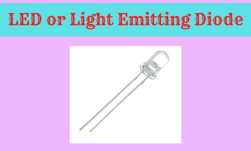
The LED is a two-terminal semiconductor light source that emits light when current flows through it. The word LED meaning or LED full form is Light Emitting Diode. The Light Emitting Diode is a special type of p-n junction diode which is made of special type doped semiconductor materials. The LED or Light Emitting Diode allows the flow of current in the forward direction and blocks the current in the reverse direction. When the current flow in the forward direction then LED releases energy in the form of photons.
Light Emitting Diode or LED Pinout or Pin Diagram
LED Consists of two terminals. These are one is positive or anode and another one is negative or cathode. LED has three different methods to identify its terminals.
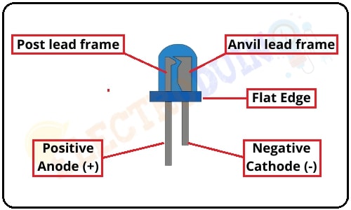
- The Long terminal of the LED is the positive or anode (+) terminal and the short terminal of the LED is the negative or cathode (-) terminal.
- Try to find the flat edge on the LED outer casing. The terminal or pin nearest the flat edge is a negative or cathode terminal or pin. And the other one is a positive or anode terminal or pin.
- If LED is transparent to look inside. So, we can easily identify by the lead frame. The anvil lead frame connected to the cathode terminal and the post lead frame is connected to the anode terminal.
Light Emitting Diode or LED Symbol
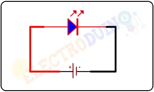
The Light Emitting Diode symbol is similar to the p-n junction diode, but it has outward arrows, which is made different from the p-n junction diode symbol.

Construction of LED or Light Emitting Diode
If we try to look at the inside of a 5mm crystal clear LED, we will see two lead frames, one lead frame connected to the cathode terminal, it is known as the anvil lead frame, and another lead frame is connected to the anode terminal, it is known as the post lead frame. The anvil lead frame holds the reflective cup, which holds the semiconductor material.

The semiconductor N-type region is placed at the bottom so it’s connected to the cathode terminal through Anvil lead frame. But the semiconductor P-type region is placed at the top. So, there’s just a wire that connects it to the anode terminal through the post lead frame.
This total mechanism is covered by a transparent solid and plastic epoxy resin hemispherical shaped shell body that protects the LED from atmospheric disturbances, vibrations, and thermal shock.
The construction of a light-emitting diode or LED is very simple to understand, it is made by depositing the three layers of semiconductor material on a substrate. These three semiconductor material layers are made in three different regions. The top layer is called the P-type region, the Middle layer is called the active region and the last or bottom layer is called the N-type region. The N-type region has free elections, the P-type region has holes and the active region has both free electrons and holes. The active region also has known as the Depletion region.
When the flow of current in the forward direction in LED (LED is forward biased), then the free electrons from n-type semiconductor and the holes from p-type semiconductor are pushed towards the active region. When free electrons and holes recombine with the opposite charge carriers in the active region, then energy release in the form of invisible or visible light.
LED Working Principle
The LED Light Emitting Diode works like a regular diode. It allows the flow of current in the forward direction (forward biased) and blocks the current in the reverse direction (reverse biased). The LEDs can emit light when it is in the forward bias condition.
When the LED’s anode (positive) terminal is connected to the positive terminal of dc power supply and the cathode (negative) terminal is connected to the negative terminal of dc power supply then the PN junction is forward biased.
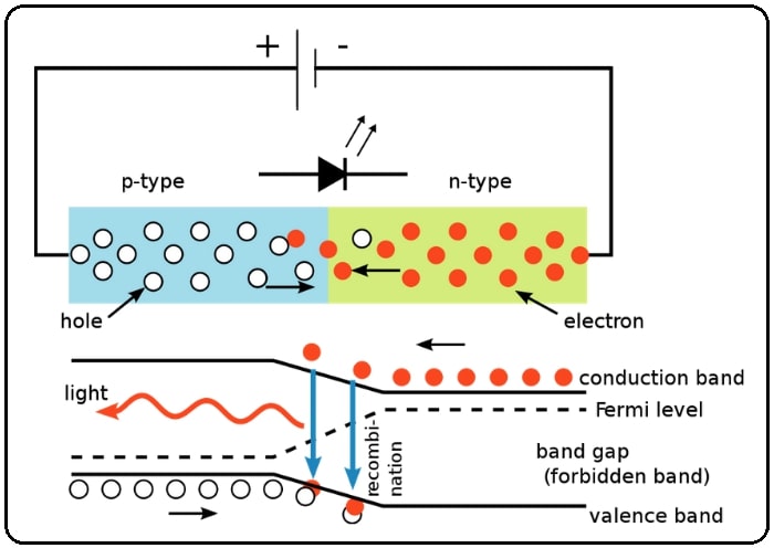
When an LED is forward biased, then the free electrons from the N-type region gain enough energy to cross the junction and recombine with the holes in the P-type region. Initially, free electrons from the N-type region are in the conduction band but as they cross over into the P-type region, they release energy and fall into a hole in the valence band. As a result, this energy released in the form of light. But, normal silicon diode is released energy in the form of heat.
LED color
The different types of semiconductor materials combinations are used to manufacture LEDs. These semiconductor materials are Gallium Arsenide (GaAs), Gallium Phosphide (GaP), or Gallium Arsenide Phosphide (GaAsP). The color of light changes depends on the change in material. The combinations of different types of materials can produce a unique wavelength of color.
| Light Color | Wavelength Range (nm) | Forward Voltage (v) | semiconductor materials |
| Ultraviolet | <400 | 3.1 - 4.4 |
Aluminium Nitride (AlN) Aluminium Gallium Nitride (AlGaN) Aluminium gallium Indium Nitride (AlGaInN) |
| Violet | 400 – 450 | 2.8 - 4.0 | Indium gallium Nitride (InGaN) |
| Blue | 450 – 500 | 2.5 - 3.7 | Zinc Selenide ((ZnSe) Indium Gallium Nitride (InGaN) Silicon Carbide (SiC) Silicon (Si) |
| Green | 500 – 570 | 1.9 4.0 | Aluminium Gallium Indium Phosphide (AlGaInP) Aluminium Gallium Phosphide (AlGaP) Indium Gallium Nitride (InGaN) |
| Yellow | 570 – 590 | 2.1 - 2.2 | Gallium Arsenide Phosphide (GaAsP) Aluminium Gallium Indium Phosphide (InGaAlP) Gallium Phosphide (GaP) |
| Orange /Amber | 590 – 610 | 2.0 - 2.1 | Gallium Arsenide Phosphide (GaAsP) Aluminium Gallium Indium Phosphide (InGaAlP) Gallium Phosphide (GaP) |
| Red | 610 – 760 | 1.6 - 2.0 |
Aluminium Gallium Arsenide (AlGaAs) Aluminium Gallium Indium Phosphide (InGaAlP) Gallium Phosphide (GaP) |
| Infrared | > 760 | < 1.9 | Gallium Arsenide (GaAs) Aluminium Gallium Arsenide (AlGaAs) |
Types of LEDs
Light Emitting Diode can be classified as two major categories of LEDs. They are
- Visible LEDs
- Invisible LEDs
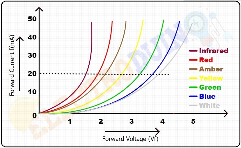
led I-V characteristics
Light Emitting Diode is an output device, when current flow through it, then it emits light. Its output light intensity depends on the forward current passing through the LED. The relation is output light intensity being directly proportional to the forward current.
Light Emitting Diode will be connected in a forward bias across the power supply. It means LED positive terminal has to be connected to the power supply positive terminal and the negative terminal connected to the power supply negative terminal. We should connect a resistor in series for current limited, which protects it from the excess current flow. We should be never connected directly to the power supply because high amounts of current will flow through it and LED may be damage.
Each Light Emitting Diode has its own forward voltage drop across the PN junction. This parameter is determined by the semiconductor material used in the manufacturing of an LED for a specified amount of forward current. Normally the forward current of an LED is about 20mA.
The I-V characteristics of the different color LEDs show below
Advantages of Light Emitting Diode
- It is a fast operating component
- Light Emitting Diodes consume less power and operate by the low dc power supply.
- It is available in various colors and sizes
- temperature range from 00C -700C
Disadvantages of Light Emitting Diode
- The LEDs may get damaged when the current is crossed a certain limit.
- Ambient temperature dependence of radiant output power and wavelength of the Light Emitting Diode.
Application of LED
- Indication
- Lighting Products
- LED Displays
- Electronic projects

