Optical Smoke Detector Circuit using ITR8102 Sensor
Hello friends! Welcome back to ElectroDuino. This blog is based on Optical Smoke Detector Circuit using ITR8102 Opto Isolator sensor. Here we will discuss Introduction to Optical Smoke Detector, Project Concept, Block Diagram, Components Required, Circuit Diagram, Working Principle.
Introduction
Smoke detector systems are one of the most important devices, we all have need to install these types of devices in our houses, buildings, and offices. Fire accidents are the most common in these days, these devices can warn us if fire accidents happen. So it can save thousands of lives. Normally two types of Smoke detector systems are available in the market one is an Optical (photoelectric) Smoke Detector and another one is Ionization Smoke Detector. In this tutorial, we will learn how to make an Optical (photoelectric) Smoke Detector. An optical smoke Detector is also known as a photoelectric smoke Detector, it works using the light scatter principle.
Project Concept
Basically, Optical Smoke Detector Circuit consists of 5 key components, these are ITR8102 Opto Isolator sensor, LM358, BC547 Transistor, LED, and Buzzer. The ITR8102 Opto Isolator sensor consists of an IR transmitter and an NPN silicon phototransistor in a single plastic housing. Its logic level changes depending on the detecting and doesn’t detect the Infrared light by the photodiode. In this project, we will use this Sensor for smoke detection. The LM358 Op-Amp IC is a Comparator IC, which compares the logic Level coming from the ITR8102 sensor and generates Output. Here the BC547 Transistor works as a switch, it is operated by the output of the LM358 Comparator IC. It is used to turn on and off the LED and Buzzer. Here the LED and Buzzer are used as an indicator when the system will detect smoke then it is turned ON.
Block Diagram of Optical Smoke Detector Circuit

Components Required
| Components Name | Quantity |
| LM358 Op-Amp IC (U2) | 1 |
| ITR8102 Opto Isolator sensor (U1) | 1 |
| BC547 Transistor (Q1) | 1 |
| 1K ohm Resistor (R1, R5) | 3 |
| 100 ohm Resistor (R2) | 1 |
| 10k ohm Resistors (R3) | 1 |
| 220 ohm Resistor (R4) | 1 |
| 5K ohm Potentiometer (VR1) | 1 |
| 10K ohm Potentiometer (VR2) | 1 |
| 100µF Capacitor (C1) | 1 |
| Green LED (LED1) | 1 |
| Red LED (LED2) | 1 |
| Buzzer (B1) | 1 |
| 9v Power Supply | 1 |
| PCB board | 1 |
| Connecting Wire | As required in the circuit diagram |
Tools Required
| Tools Name | Quantity |
| Soldering Iron | 1 |
| Soldering wire | 1 |
| Soldering flux | 1 |
| Soldering stand | 1 |
| Multimeter | 1 |
| Desoldering pump | 1 |
| Wirecutter | 1 |
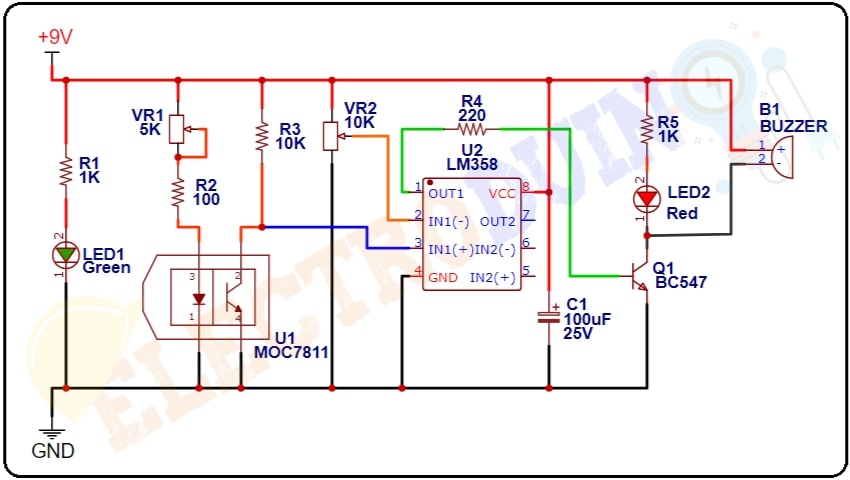
Optical Smoke Detector Circuit Diagram
Working Principle of Optical Smoke Detector Circuit using ITR8102 Opto Isolator sensor and LM358
When we connect the 9v power supply to the circuit. At the same time, the ITR8102 Opto Isolator sensor is also activated, then the sensor’s IR transmitter start emitting Infrared light and the phototransistor starts detecting this Infrared light. When the phototransistor detects Infrared light, then the sensor output is Low (0v) and when it does not detect, then the sensor output goes High (9v).
The LM358 Op-Amp IC compares the input voltage between the Inverting input (IC pin 2) and the Non-Inverting input (IC pin 3) and generates output. A 10K potentiometer is connected to the Inverting input (IC pin 2) of this IC, which is used to set a reference voltage at this pin.
When a fire breaks out smoke, then it will enter the gap (slotted area) of the Opto-interrupter sensor. So, the phototransistor is unable to detect Infrared light. For this reason, the sensor produces High output which goes to the Non-inverting input (IC pin 3) of the LM358 IC. This output voltage is greater than the reference voltage. So, the IC gives High output which is going to the base terminal of the BC547 transistor. Then the Transistor comes into active mode, and it starts conducting and connect the LDR and Buzzer negative terminal to the Ground. So, the Red LED starts glowing and Buzzer generates sound. It indicates smoke is detected.