Wireless Power Transmission Project using 555 Timer IC
Hello friends! Welcome back to ElectroDuino. This blog is based on Wireless Power Transmission Project Circuit using 555 Timer IC. Here we will discuss Introduction to Wireless Power Transmission Project, Project Concept, Block Diagram, Components Required, Circuit Diagram, and Working Principle.
Introduction
In these modern days, Researchers are researching different new technology in the Electronic fields, the wireless power transmission technology is the most popular among them. Several types of technology are being tested and used in different electronic devices, the most popular application of this technology is the wireless Mobile charging system. In this blog tutorial, we will design a Wireless Power Transmission Project and learn how it works. The working method of this technology is, two objects having the same resonant frequency and in magnetic resonance at powerfully coupled rule tends to exchange the energy, while dissipating relatively little energy to the extraneous off-resonant objects.
Project Concept Wireless Power Transmission Project
This project is divided into two parts, one is the Transmitter, and another one is the Receiver. The Transmitter part converts the input voltage into magnetic flux and the Receiver part converts this magnetic flux into DC output voltage.
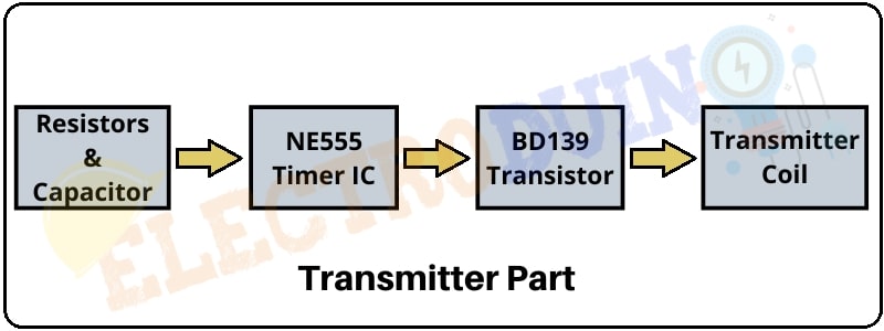
- Transmitter Part consists of Resistors & Capacitor, 555 Timer IC, BD139 Transistor, and Primary Coil. The resistors & capacitors are connected to the 555 Timer IC and the IC producing a pulse output. The BD139 Transistor work as a switching device, that control by the IC output, and it is used to produce oscillations in the Primary Coil. Primary Coil produces the DC bias magnetic flux.
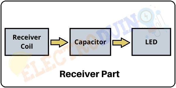
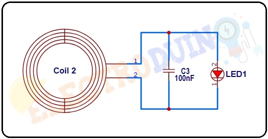
- The receiver Part consists of a Secondary Coil, capacitor, and LED. The Secondary Coil comes into this magnetic flux, then power transfer from Primary Coil to the Secondary Coil. This Power filter by the capacitor and turned on the LED.
Block Diagram of Wireless Power Transmission Project Circuit using 555 Timer IC
Transmitter
Receiver
Components Required
| Components Name | Quantity |
| NE555 Timer IC | 1 |
| BD139 Transistor (Q1) | 1 |
| 1.2K ohm Resistor (R1) | 1 |
| 10k ohm Resistors (R2) | 1 |
| 100 ohm /25 Watt Resistor (R3) | 1 |
| 3.3nF Capacitor (C1) | 1 |
| 0.01µF Capacitor (C2) | 1 |
| 100nF Capacitor (C3) | 1 |
| LED (LED1) | 1 |
| Coil (30 SWG, enameled copper wire with 5CM diameter / 30 turns) | 2 |
| Power Supply Between 3 to 5v | 1 |
| PCB board | 2 |
| Connecting Wire | As required in the circuit diagram |
Note: Transmitter and Receiver coils are built by winding 30 turns of 30 SWG enameled wire on 5cm diameter. These coils are should be the same on both sides of the circuit, otherwise, it will not work properly.
Tools Required
| Tools Name | Quantity |
| Soldering Iron | 1 |
| Soldering wire | 1 |
| Soldering flux | 1 |
| Soldering stand | 1 |
| Multimeter | 1 |
| Desoldering pump | 1 |
| Wirecutter | 1 |
Circuit Diagram of Wireless Power Transmission Project using 555 Timer IC
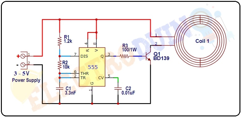
Transmitter Part
Receiver Part
Working Principle of Wireless Power Transmission Project Circuit
- The NE555 Timer IC is the main chip of the Transmitter Part. Here it is configured as an astable multivibrator that producing a particular pulse output from Pin 3. This output pulse control by the resistor(R, R2) and Capacitor (C1), which is connected to the IC. In this circuit the IC Frequency of oscillation 20KHz. This output goes to the base terminal of the BD139 Transistor that works as a switching device. Primary Coil (Coil1) one terminal is connected to the collector terminal of the transistor. The Primary Coil produces the DC bias magnetic flux around it.
- When we place the Secondary Coil (Coil 2) in front of the Primary Coil, then Coil 2 comes into the magnetic flux. Then it induces this magnetic flux into Alternate power in the receiving coil. This induces an Electric field that will turn on the LED. This is the Alternate power source, so we can connect LEDs in any polarity in this Rx circuit. If you want a dc output then you can connect a rectifier circuit with the coil.