Introduction to L293D Motor Driver Shield | How it’s works
Hello friends! Welcome back to ElectroDuino. This blog is base on Introduction to L293D Motor Driver Shield | How it’s work. Here we will discuss the Introduction to L293D Motor Driver Shield, hardware overview, pin diagram, Working Principle, Features, and applications.
Introduction
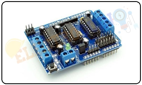
The L293D Motor driver shield is one of the best ways for controlling DC motor, Servo motor, and Stepper motors in a single board. It can control the rotation direction and speed of four DC motors, two Servo motor, and two Stepper motors. It is easy to connect with an Arduino UNO or MEGA. This shield especially using Arduino projects like robotics and CNC. This module consists of two L293d dual-channel H-Bridge motor driver IC and a 74HC595 shift register IC
L293D Motor Driver Shield Hardware Overview
L293d motor driver IC
The L293D is a dual-channel H-Bridge motor driver. A single IC is able to control two DC motors or one stepper motor. The L293D is designed to provide bidirectional drive currents of up to 600-mA at voltages from 4.5 V to 36 V. and Peak Output Current 1.2 A Per Channel. This IC has two enable inputs, these are provided to enable or disable the device independently of the input signals.
The motor driver shield has two L293D motor driver IC. So, the L293d shield able to control four DC motors or one stepper motor.
74HC595 shift register IC
The 74HC595 is a shift resistor IC. This IC has an 8-bit shift register and an 8-bit D-type latch with three state parallel outputs. This shift register can accept serial data and provides a serial output. Also, it can provide parallel data to the 8-bit latch. The shift register and latch have independent clock inputs.
The shield has a 74HC595 shift register that extends Arduino 4 digital pins to the 8 direction control pins of two L293D chips.
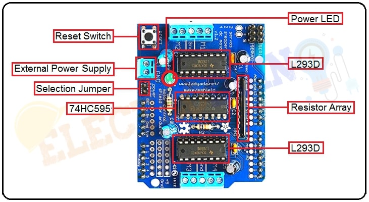
Reset Switch
The RESET is nothing but the Arduino reset button. This switch works same as the Arduino reset and it is used to reset the Arduino board. It just brought up top for easy to use purpose.
Power LED
The on-board Power LED indicates the motor’s power supply. If the power supply is on the LED is turned on, the motor will work well. If the LED will not ON, it means the power supply is OFF. So, the motors will not be working.
Resistor Array
The shield comes with a pulldown resistor array, that keeps motors switched off during power-up.
External Power Supply
The shield has a 2-pin terminal block for External Power Supply. It used to DC power supply for motors.
It also can be used to the power supply to the Arduino board, it possible by the “Power Supply Selection Jumper”.
Power Supply Selection Jumper
- Single DC power supply for both Arduino and motors
If you want to provide a single DC power supply for both Arduino and motors. So, Place the power jumper on the motor shield. Now you can simply connect the power supply to the DC jack on the Arduino or the 2-pin External Power Supply terminal block on the shield.
But, this method only used when the motor supply voltage is less than 12V.
- Arduino powered through USB and motors through an External Power Supply pin
If you want to powered the Arduino board through the USB and the motors powered through the DC power supply. At first, plug in the USB cable, then connect the motor supply to the external Power. Now you can turn on the power supply one by one (first the Arduino power supply then the motor power supply). In this condition do not place the jumper on the shield.
- Two separate DC power supplies for the Arduino and motors
If you want to use two separate power supplies for the Arduino boards and motors. So, at first, you need to connect the power supply to the DC jack on the Arduino, Then connect the motor power supply to the 2-pin External Power Supply terminal block on the shield. Make sure the jumper is removed from the motor shield.
L293D Motor Driver Shield PinOut
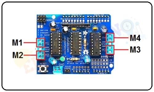
- PinOut for DC motors
| SL. NO | Pin Name | Description |
| 1 | M1 | M1 is output for Motor 1, Connect Motor 1 |
| 2 | M2 | M2 is output for Motor 2, connect Motor 2 |
| 3 | M3 | M3 is output for Motor 3, connect Motor 3 |
| 4 | M4 | M4 is output for Motor 4, connect Motor 4 |
- PinOut for Stepper motors
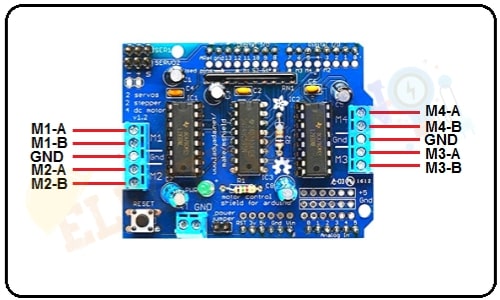
| SL. NO | Pin Name | Description |
| 1 | M1-A, M1-B, GND, M2-A, M2-B | Output for Stepper Motor 1, connect stepper motors (unipolar or bipolar) with single coil, double coil, or interleaved stepping |
| 2 | M3-A, M3-B, GND, M4-A, M4-B | Output for Stepper Motor 2, connect stepper motors (unipolar or bipolar) with single coil, double coil, or interleaved stepping |
- PinOut for Servo motor
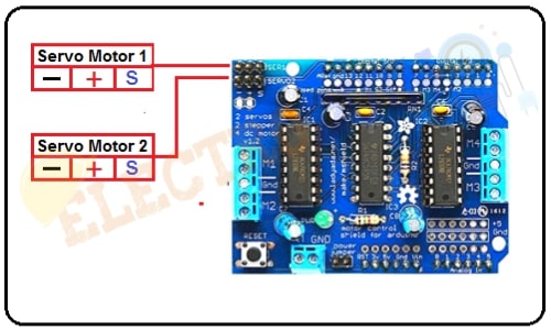
| SL. NO | Pin Name | Description |
| 1 | Servo 1 Pin (-,+,s) | Output for Servo motor 1, Connect the servo motor pin GND, VCC, SIGNAL respectively |
| 2 | Servo 2 Pin (-,+,s) | Output for Servo motor 2, Connect the servo motor pin GND, VCC, SIGNAL respectively |
| Note: Digital pins D2, D13, and analog pins A0-A5 are not used by the shield. It can be used to connect other sensors or circuits. |
Motor Driver Shield Features
- 2 connections for 5V ‘hobby’ servos connected to the Arduino’s high-resolution dedicated timer
- 4 H-Bridges: L293D chipset provides 0.6A per bridge (1.2A peak) with thermal shutdown protection, internal kickback protection diodes. Can run motors on 4.5VDC to 25VDC.
- Up to 4 bi-directional DC motors with individual 8-bit speed selection (so, about 0.5% resolution)
- Up to 2 stepper motors (unipolar or bipolar) with single coil, double coil, or interleaved stepping.
- Pull-down resistors keep motors disabled during power-up
- Big terminal block connectors to easily hook up wires (18-26AWG) and power
- Arduino reset button brought up top
- 2-pin terminal block and jumper to connect external power, for separate logic/motor supplies
- Tested compatible with Arduino Mega 1280 & 2560, Diecimila, Duemilanove, and UNO
Applications
- DC motors Control.
- Stepping motors Control.
- Servo Motor Control.
- In many Robotics projects.
- CNC projects.