
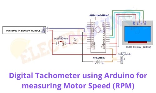
Digital Tachometer using Arduino for measuring Motor Speed (RPM)
Hello friends! Welcome back to ElectroDuino. This blog is based on Digital Tachometer using Arduino for measuring Motor Speed (RPM). Here we will discuss Introduction to Digital Tachometer using Arduino, Project Concept, Block Diagram, components required, circuit diagram, working principle, and Arduino code.
Introduction
Normally we have to think measuring the Speed (rpm) of a motor or rotating body is too much difficult. Don’t worry, this project can solve this problem. A tachometer is an electronic device that can measure the rotation speed of a shaft or disk, as in a motor or other machine. It measures the number of revolutions of an object in a given interval of time. Usually, it is expressed in revolutions per minute or RPM and displays the revolutions per minute (RPM) on an analog dial or digital display.
Project Concept
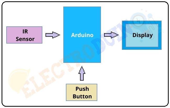
The key components of this project are the IR sensor module, Pushbutton, Arduino, and Display. This project work is based on the detection or not detection of the infrared light by the IR sensor module. we will use some sort of reflecting material on the rotating body, which could detect a peak of the sensed infrared light and measure the time between those peaks. The measured time is the time that the rotating body takes to make one full rotation. The RPM calculation by the time measurement process is done by the Arduino. The push-button switch is used to Arduino low power mode enable and disable. This helps to low power consumption. When we measure RPM this time we need to press (on) the push button switch. When we get the reading (RPM value), then we can release the push button, then the Arduino will be in low power mode and OLED Display is turn off. We can see the RPM value on the display.
Block Diagram
Components Required
| Components Name | Quantity |
| Arduino Nano | 1 |
| TCRT5000 IR Sensor Module (You can use the normal IR Sensor Module) | 1 |
| 0.96 inch I2C OLED display | 1 |
| Push Button Switch | 1 |
| 1 k ohm Resistor | 1 |
| Slide Switch | 1 |
| 9V Battery with Battery connector | 1 |
| PCB Zero board | 1 |
| Connecting wires | As required in the circuit diagram |
Tools Required
| Tools Name | Quantity |
| Soldering Iron | 1 |
| Soldering wire | 1 |
| Soldering flux | 1 |
| Soldering stand | 1 |
| Multimeter | 1 |
| Desoldering pump | 1 |
| Wirecutter | 1 |
Required Library
Download the Adafruit_GFX.h library here: CLICK
Download the Adafruit_SSD1306.h library here: CLICK
Circuit Diagram of Digital Tachometer using Arduino

Circuit Wiring
| Components Pin | Arduino pin |
|
IR Sensor Module Vcc Pin, OLED Display Vcc Pin, Push Button Switch terminal-1 |
Arduino 5V Pin |
|
IR Sensor Module GND Pin, OLED Display GND Pin |
GND (ground) Pin |
| Push Button Switch terminal-2 | Connected to GND (ground) Pin through 1k resistor |
| IR Sensor Module Data pin | Digital Pin “D7” |
| OLED Display SCL pin | Analog Pin “A5” |
| OLED Display SDA pin | Analog Pin “A4” |
| Push Button data pin is the junction point of terminal-2 and resistor | Digital Pin “D5” |
| 9v Battery positive (+) terminal | Connected to VIN Pin through a Slide Switch for external DC Power supply to operating Arduino. |
| 9v Battery negative (+) terminal | GND (ground) Pin |
Working of Digital Tachometer using Arduino and IR Sensor
After connecting all the components according to the circuit diagram, now time to turn on the circuit power supply using turn on the slide switch.
Here we are using the IR Sensor Module, which is works as an obstacle detector. We all know that the IR sensor emits and received Infrared light to detect objects. Also, we know that a black surface can’t reflect light, and a white surface is a good light reflector. That’s why we will use a black & white disc, which we will connect any rotating body. Here we will measure a dc motor RPM so we will connect this disk with the motor shaft.
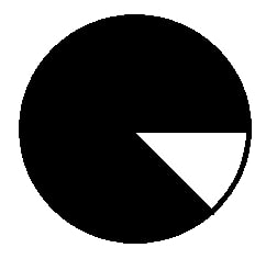
When the black surface comes in front of the IR sensor, this time infrared light does not reflect back to the sensor. So the sensor does not detect and sensor output is High (1/+5v). When the White surface comes in front of the IR sensor, this time infrared light reflects back to the sensor. So the sensor detects the surface and the sensor output is Low (0/GND). When the motor shaft starts rotating then also this disc starts rotating. This time if we place the IR sensor in front of the disk then the IR sensor generates Output in a particular square waveform. This square waveform output depends on the IR sensor detection time.

The Arduino has to start a counter when the IR sensor detects the first positive edge representing the final of the white surface and counts the time till the IR sensor detects another positive pulse, representing the start of the white surface again. Then the Arduino makes the difference of the measure counters and it checks the motor takes how much time for one rotation in microseconds. Using the Arduino code we divide one minute (60.000.000 us) by that value and Then we get the RPM value. The Arduino print that RPM values on the OLED display.
The push-button switch takes an important role in the project. When we measure RPM this time we need to press (on) the push button switch. When we get the reading (RPM value), then we can release the push button, then the Arduino will be in low power mode and OLED Display is turned off. In this way, we can save power without turn off the circuit by the slide switch.
Digital Tachometer using Arduino Code
//For low power mode
#include <avr/sleep.h>
#include <avr/power.h>

//OLED Display libraries
#include <SPI.h>
#include <Wire.h>
#include <Adafruit_GFX.h>
#include <Adafruit_SSD1306.h>

#define OLED_RESET 4
Adafruit_SSD1306 display(OLED_RESET);

//In and Out
int IRsensor = 7;
int pushbutton=5;
//Variables
unsigned long duration = 0;
float rpm = 0;
float rpm_a = 0;
int counter = 0;
int present = 0;
int previous = 0;
unsigned long elapsed = 0;
unsigned long elapsed_prev = 0;
int disabled = 0;


void setup()
 {
  Serial.begin(9600); // Start serial communication between arduino and your computer

  pinMode(IRsensor,INPUT); // Set IRsensor pin as INPUT
  pinMode(pushbutton,INPUT); // Set pushbutton pin as INPUT

  // by default, we'll generate the high voltage from the 3.3v line internally! (neat!)
  display.begin(SSD1306_SWITCHCAPVCC, 0x3C);  // initialize with the I2C addr 0x3D (for the 128x64)


  // Clear the buffer.
  display.clearDisplay();

  // Print text and RPM value on display
  display.clearDisplay();
  display.setTextSize(1);
  display.setTextColor(WHITE);
  display.setCursor(0,0);
  display.println("ELECTRODUIN0 RPMmeter"); // Print text
  display.display();
  display.setTextSize(2);
  display.setTextColor(WHITE);
  display.setCursor(0,19);
  display.println("RPM:");
  display.setCursor(80,19);
  display.println(rpm);  // Print RPM Value
  display.display();

  //We print the ELECTRODUINO logo
  scrollENlogo();

  elapsed = micros();
 }


void loop()

 {
  if(digitalRead(pushbutton))
    {
     //Arduino low power enabled
     if(disabled==0)
      {
       sleep_disable();
       disabled = 1;
      }
///////////////////////one rotation measure///////////////////
     if (digitalRead(IRsensor) == 1 && previous == 0)
      {
       previous = 1;
       duration = elapsed - elapsed_prev;
       elapsed_prev  = micros();
       }
     if (digitalRead(IRsensor) == 1 && previous == 1)
      {
       previous = 1;
      }
     if (digitalRead(IRsensor) == 0 && previous == 1)
      {
       previous = 0;
      }
     if (digitalRead(IRsensor) == 0 && previous == 0)
      {
       previous = 0;
       elapsed = micros();
       }
//////////////////////////////////////////////////////////////


   rpm = 60000000/duration;
//We add a small error in the rpm value (in this case +-2)
 if ( (rpm_a-2) < rpm  &&  rpm < (rpm_a+2))
 {
  rpm_a = rpm;
  counter = counter +1;
  if (counter == 50)
  {
     // text display tests
    display.clearDisplay();
    display.setTextSize(1);
    display.setTextColor(WHITE);
    display.setCursor(0,0);
    display.println("ELECTRONOOBS RPMmeter");
    display.setTextSize(2);
    display.setTextColor(WHITE);
    display.setCursor(0,19);
    display.println("RPM:");
    display.setCursor(80,19);
    display.println(rpm);
    display.display();
    counter = 0;
  }
 }

  if (!( (rpm_a-2) < rpm  &&  rpm < (rpm_a+2)))
  {
  rpm_a=rpm;
  }
 }//end if pushbutton=1


 else
  {
  //Variables
  display.display();
  display.clearDisplay();
  delay(10);
  duration = 0;
  rpm = 0;
  rpm_a = 0;
  counter = 0;
  present = 0;
  previous = 0;

  //Arduino low power enabled
  set_sleep_mode (SLEEP_MODE_PWR_DOWN);
  sleep_enable();
  disabled = 0;
 }//end pushbutton =0
 }//end of void loop


void scrollENlogo(void)
 {
  display.setTextSize(1);
  display.setTextColor(WHITE);
  display.setCursor(7,0);
  display.clearDisplay();
  display.println("ELECTRODUINO");
  display.setTextSize(2);
  display.setTextColor(WHITE);
  display.setCursor(0,10);
  display.println("WELCOME");
  display.display();
  delay(1);

  display.startscrolldiagright(0x00, 0x07);
  delay(5000);
  display.stopscroll();

}


