
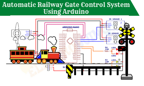
Automatic Railway Gate Control System Using Arduino, IR Sensor
Hello friends! Welcome back to ElectroDuino. This blog is based on How to Make an Automatic Railway Gate Control System Using Arduino, IR Sensor & servo motor. Here we will discuss the Introduction to Automatic Railway Gate Control System, Project Concept, Block Diagram, Components Required, Circuit diagram, Working Principle, and Arduino Code.
Introduction
Railway Gate is very essential for security purposes. If there has any defect in the system it will damage one or more life. Every year thousands of accidents occur on railway crossings and thousands of people are dying. Here we are making a circuit by which the Gate will be operated by itself. This project will make the system more reliable and precise.
Project Concept
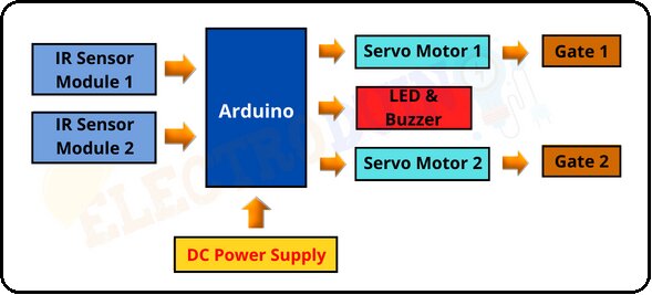
The Automatic Railway Gate Control System project concept is very simple. The key components of the project are the IR sensor, Arduino microcontroller, servo motor, LEDs, and Buzzer.
In this project, two IR Sensor works like the eyes of the project. It detects the train position. Two Servo motors are used to open and close the railway crossing gate. Also, we will use the Arduino microcontroller board, which is the brain of the project. It controls the whole system. Finally, LEDs and buzzer are used as an indicator.
When one of the IR sensors detects the train the system closes the gate automatically and indicated by the red LED and buzzer. When the sensors are doesn’t detect the train, then the system will open the gate automatically and indicated by the Yellow LED.
This project is sponsored by PCBWay.com. It’s a Professional grate PCB prototype service company. They are providing you 10 high-quality PCBs at only 5$. At first register on the website, then fill in all the specifications like Dimensions, Layers, Thickness, color, and Quantity. In the last upload your Gerber files and place your Order Now. After completing all the processes, they produce your PCB prototype within 24 hours.
So, order now to get a high-quality PCB prototype quickly from PCBWay.com

Block Diagram of Automatic Railway Gate Control System Using Arduino, IR Sensor
Components Required
| Components Name | Quantity |
| Arduino Nano | 1 |
| IR Sensor Module | 2 |
| Sg-90 Servo Motor | 2 |
| 150-ohm Resistor | 2 |
| Red LED (D1 & D2) | 2 |
| Yellow LED (D3 & D4) | 2 |
| Buzzer | 1 |
| Toggle or Slide switch | 1 |
| 9-volt Battery with Battery Connector | 1 |
Circuit Diagram of Automatic Railway Gate Control System Using Arduino
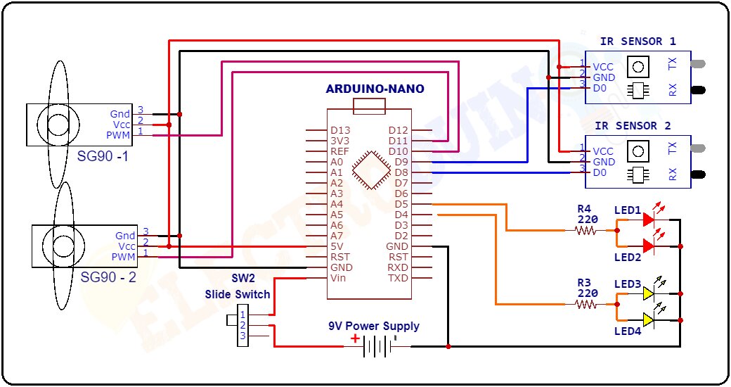
Circuit Wiring
| Components Pin | Arduino Pin |
| 9-v battery positive(+) terminal | VIN Pin through the slide-switch(SW1) |
| 9-v battery negative(-) terminal | GND(ground) Pin |
| IR Sensor 1, 2 and Servo motor 1, 2 Vcc Pin | 5v pin |
| IR Sensor 1, 2 and Servo motor 1, 2 GND Pin | GND (ground) pin |
| IR Sensor 1, 2 OUT Pin | Analog pins A1 and A2 serially |
| Servo motor 1, 2 PWM Pin | Digital pin D5 and D6 serially |
| Buzzer positive terminal | Digital pin D3 |
| LED D1 & D2 Positive terminal | LED D1 & D2 Positive terminals are shorted and connected to the Digital pin D11 Pin through The Resistor(R1) |
| LED D3 & D4 Positive terminal | LED D3 & D4 Positive terminals are shorted and connected to the Digital pin D12 Pin through The Resistor(R2) |
| Buzzer and LED D1, D2, D3 & D4 ground terminal | GND (ground) pin |
Working of Automatic Railway Gate Control System
First of all, we need to place the components correct position for the perfect work of this system. Two IR sensors are placed on both sides of level crossings and the distance between the two IR sensors is dependent on the length of the train. Two Servo motors are placed on both sides of the railway track.
When the train comes in front of the IR sensor-1. Then IR sensor-1 detects the arrival of the train and produces Low(0) output from its Data Pin. But, on the other side, the IR Sensor-2 output is HIGH (1) because this time sensor-2 does not detect the train. When the Arduino gets this signal from two sensors, then the Arduino sends the PWM signal to the servo motors. As a result, servo motors start working and close the gate. At this time, the Arduino sends commands to turn on Red LED and the buzzer starts to generate beep-beep sound, which means that the train is coming.
When the train crosses the level crossing and the train comes in front of the IR sensor-2. Then IR sensor-2 detects the arrival of the train. So, the sensor-2 output goes LOW(0). But, on the other side, the IR Sensor-1 output is HIGH (1) because this time sensor-1 does not detect the train. When the Arduino gets this signal from two sensors, then again the Arduino sends the PWM signal to the servo motors. As a result, the servo motors back to the first position, and automatically open the gate. This time Yellow LED will turn on and the buzzer will stop, it means that the train is gone.
When IR sensor 1 and IR sensor 2 does not detect the train, then the output of the sensor is High (1). In this condition, the gate is open and the Yellow LED will turn on and the buzzer will stop, it means that the train does not come.
Arduino Code for Automatic Railway Gate Control System
/*Automatic Railway Gate Control System Using Arduino, IR & servo
 electroduino.com */
#include <Servo.h>
const int IRsensor1 = A2;
const int IRsensor2 = A1;
const int BUZZER = 10;
const int Rled = 11;
const int Gled = 12;

Servo myservo1;
Servo myservo2;

void setup()
{
  pinMode(IRsensor1, INPUT);
  pinMode(IRsensor2, INPUT);
  pinMode(BUZZER, OUTPUT);
  pinMode(Rled, OUTPUT);
  pinMode(Gled, OUTPUT);

  myservo1.attach(5); // Servo motor 1 pin connected to D5
  myservo2.attach(6); // Servo motor 2 pin connected to D5

  }
void loop()
 {
   int Sensordata1 = digitalRead(IRsensor1); // read degital data from IR sensor1
   int Sensordata2 = digitalRead(IRsensor2); // read degital data from IR sensor2
   myservo1.write(0); // sets the servo at 0 degree position
   myservo2.write(0); // sets the servo at 0 degree position

  if (Sensordata1 == LOW && Sensordata2 == HIGH)
   {
    myservo2.write(90);     // sets the servo at 90 degree position
    myservo1.write(90);     // sets the servo at 90 degree position
    digitalWrite(BUZZER, HIGH); // turn on buzzer
    digitalWrite(Rled, HIGH); // turn on Red LED
    delay(3000);
   }
  else if (Sensordata1 == HIGH && Sensordata2 == LOW)
   {
    myservo1.write(0);     // sets the servo at 0 degree position
    myservo2.write(0);     // sets the servo at 0 degree position
    digitalWrite(Gled, HIGH); // turn on Yellow LED
    digitalWrite(BUZZER, LOW); // turn off buzzer
    delay(3000);
   }
  else
   {
    myservo1.write(0);     // sets the servo at 0 degree position
    myservo2.write(0);     // sets the servo at 0 degree position
    digitalWrite(Gled, HIGH); // turn on Yellow LED
    digitalWrite(BUZZER, LOW); // turn off buzzer
   }

}


