Interfacing LDR Sensor with Arduino | led dimmer LDR Sensor Arduino Code for Analog Output
Hello friends! Welcome back to ElectroDuino. This tutorial is base on Interfacing LDR Sensor with Arduino | LDR Sensor Arduino Code for Analog Output Read. Here we will learn how to connect the LDR Sensor module to the Arduino circuit diagram, and LDR Sensor Arduino code for Analog Output. Also, we will make a dark & light detector project using the analog output of the sensor..
Components Required
| Components Name | Quantity |
| Arduino UNO or you can use other types of Arduino like Arduino NANO, MEGA, pro mini, etc. | 1 |
| LDR Sensor Module | 1 |
| LED (Green & Red) | 1 pcs each color |
| 220ohm Resistor | 2 |
| Connecting wires | As required in the circuit diagram |
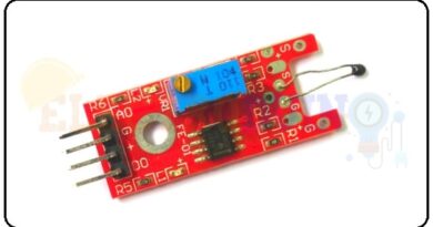
LDR Sensor Module or Photoresistor sensor Pin Diagram

How to use LDR Sensor with Arduino to Read Analog Output
Here we will connect the LDR sensor module with Arduino to read the Analog Output of the sensor. First of all, we connected the sensor Vcc pin to the Arduino 5v pin and the GND pin is connected to the GND pin. The analog output pin is connected to the Arduino analog pin to read the analog output value from the LDR sensor module.
Arduino LDR Sensor Circuit diagram for Analog Output

Circuit Wiring
| Components Pin | Arduino Pin |
| LDR sensor Vcc pin | + 5v Pin |
| LDR sensor GND pin | GND (ground) pin |
| LDR sensor AO (Digital Out) pin | Analog pin A5 |
| LED1 (Green) positive terminal | Digital pin D5 |
| LED1 (Green) negative terminal | GND pin through the 220ohm resistor. |
| LED2 (Red) positive terminal | Digital pin D4 |
| LED2 (Red) positive terminal | GND pin through the 220ohm resistor. |
How the LDR Sensor Works as a Dark & Light Detector using Sensor Digital Output value
In this circuit, the Sensor Analog Output pin is connected to the Arduino analog pin “A5”. LDR Sensor Analog Output change according to the changes of light intensity on the surface of the LDR. The sensor gives analog output value ranges from 0 to 1023 (0v to 5v), and prints this value on Arduino IDE serial monitor window. The LDR sensor gives a maximum analog output (1023) when no light falls on the surface of the LDR, and it will a minimum analog output(0) when light falls on the surface of the LDR.
The LED1(Green) and LED2(Red) are indicators, these are indicated light and dark respectively.
In the Arduino code, we need to take two analog values, one for the maximum analog value and another one for the minimum analog value. Here we will take 800 for maximum analog value and 300 for minimum analog value.
If Arduino reads analog value greater than or equal to 800 from the sensor output pin, LED2(Red) will turn ON, and LED1(Green) will turn OFF, It means that it is dark. Else if Arduino reads analog value less than or equal to 300 from the sensor output pin, LED1(Green) will turn ON, and LED2(Red) will turn OFF, It means that it is Light.
LDR Sensor with Arduino Code
/* interfacing LDR sensor with Arduino | LDR Sensor Arduino Code for Analog Output
www.electroduino.com */
 int LDRSensor = A5;
 int LED1 = 5;
 int LED2 = 4;

void setup()
 {
  pinMode (LDRSensor, INPUT);
  pinMode (LED1, OUTPUT);
  pinMode (LED2, OUTPUT);
  Serial.begin (9600);
 }

void loop()
 {
   int Sensordata = analogRead (LDRSensor);

   Serial.print("Sensor value:");
   Serial.println(Sensordata);

 if (Sensordata <= 300)
  {
   digitalWrite(LED1, HIGH);
   digitalWrite(LED2, LOW);
  }

 else if (Sensordata >= 800)
  {
   digitalWrite(LED1, LOW);
   digitalWrite(LED2, HIGH);
  }
 }
Code Analysis
|
Code Line |
Description |
|
|
It is declared that your LDR sensor’s analog output (A0) pin connected to Arduino analog pin “A5” and named as |
|
|
It is declared that the Green LED pin connected to the “D5” pin and named as |
|
|
Initialize Arduino analog pin “A5”, as an |
|
|
Initialize “D5” and “D4” pins, as |
|
|
This function starts serial communication, at 9600 bits of data per second, between your board and your computer with the line. |
|
|
The function |
|
|
This command used to print the sensor value on your serial monitor window. |
|
|
If Arduino reads the analog value “less than or equal to 300” from the sensor, then Arduino provides commands to turn ON the LED1 and turn OFF the LED2. |
|
|
Else if Arduino reads the analog value “greater than or equal to 800″ from the sensor, then Arduino provides commands to turn ON the LED2 (Red) and turn OFF the LED1. |
Output
- When high light intensity falls on the LDR, then LED1(Green) will turn ON and LED 2(Red) will turn OFF, It means that it is Light.
- When no light falls on the LDR sensor, then LED2(Red) will turn ON, and LED1(Green) will turn OFF, It means that it is dark.