
Dual Axis Joystick Module | How it’s works
Hello friends! Welcome back to ElectroDuino. This blog is base on Dual Axis Joystick Module | How it’s Works. Here we will discuss the Introduction to Joystick Module, module pin diagram, Working Principle, Features, and applications.
Introduction
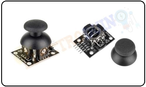
The Joystick module is an analog output device, which is used to sense movements in 2 directions (axes). These modules are mainly used in a gaming controller, Remote controller, etc. Also, we can use it in Electronic and DIY projects for controlling purposes. It allows you to control X and Y dimensions. The Joystick module consists of two potentiometers and a push-button switch. These potentiometers provide analog output value and the push button provides digital output value. It has a self-centering spring-loaded mechanism, it means when we release the joystick knob/cap it will center itself.
Joystick Module Pin Diagram
| Pin Number | Pin Name | Description |
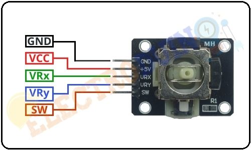
| 1 | GND | GND is the Ground Pin of the module which needs to connect the negative (ground) terminal of the 5v power supply. |
| 2 | VCC | VCC is the Positive input Pin of the module which needs to connect the positive (+) terminal of the 5v power supply. |
| 3 | VRx | This pin provides an analog output voltage range of 0 to 5v according to the movement of the joystick knob/cap in X-direction (axis). |
| 4 | VRy | This pin provides an analog output voltage range of 0 to 5v according to the movement of the joystick knob/cap in Y-direction (axis). |
| 5 | SW | SW is the Digital output from the switch. It’s normally open, it means the digital output from the SW pin will be HIGH. When the button is pressed, it will connect to GND, giving output LOW. |
Joystick Module Hardware Overview
The joystick module mainly consists of two potentiometers, one Switch, and a knob/cap
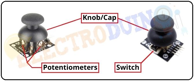
Potentiometers
The joystick module consists of two 10k Potentiometer, one for X-axis, and another one for Y-axis. Both potentiometers are independent to move in their particular direction (X and Y axis). These two potentiometers are used as dual adjustable voltage divider circuits in the module. These potentiometers are providing analog output.
The housing of these potentiometers is made of an interesting Mechanism. The Mechanism is known as Gimbal Mechanism. It is a self-centering joystick module, it means it has a spring-loaded mechanism, so when we release the joystick knob it will back to center position itself.
Switch
The joystick module consists of a Push Button Switch that activates when you pressed down on the knob. The switch is to provide Digital output. It’s normally open, it means the digital output from the SW pin will be HIGH. When the button is pressed, it will connect to GND, giving output LOW.
Knob/Cap
The joystick module has a Black color knob/cap. It helps to move the potentiometer and provide a smooth controlling experience. Also, it is used to operate the switch by the pressed down the cap.
How the 2-Axis Joystick Module Works?
The joystick module consists of two potentiometers and one Switch. According to the circuit diagram Potentiometer-VR1 represents X-axis and Potentiometer-VR2 represents Y-axis. The potentiometer is a variable resistor, when we will rotate the potentiometer knob the output voltage also changes at the signal pin. The joystick module knob is connected to these potentiometers knobs (VR1 & VR1), when we moved the module knob then the potentiometer knob is also moved, so the potentiometer output value also change. This way we can get the different Analog output values from the VRx and VRy pin of the module. So, this module provides analog output in the range of 0-1023 (0v – 5v).

Now we will connect the 5v power supply to the joystick module. When the joystick module knob is present at the center position, the module outputs from both pins (VRx & VRy) is half of VCC means 2.5 volt, so the analog output is approx 512.
If the joystick knob is moved to the end of the +X-axis then the VRx pin output is 1023 (5v) and the VRy pin output is 512 (2.5v). If the joystick knob is moved to the end of the -X-axis then the VRx pin output is 0 (0v) and the VRy pin output is 512 (2.5v).
If the joystick knob is moved to the end of the +Y-axis then the VRy pin output is 1023 (5v) and the VRx pin output is 512 (2.5v). If the joystick knob is moved to the end of the -Y-axis then the VRy pin output is 0 (0v) and the VRx pin output is 512 (2.5v).
Normally the SW pin output is Low(0). When we press the Knob then the SW pin output is High (1).

Technical Specifications and Features
| Parameter | Value |
| Operating Voltage | 5V |
| Internal Potentiometer value | 10K |
| Operating temperature | 0 to 70 °C |
| Potentiometer Outputs | Analog outputs range of 0 to 1023 (0v – 5v) |
| Pushbutton Output | Digital output Active Low |
| Dimensions | 40 x 27 x 15 (LxWxH) mm |
| Weight | 10gm (without Hat) |
Application
- Game Input/Control
- Robot Control
- Use in DIY projects


