Motor Driver IC L293D | How it’s work
Hello friends! Welcome back to ElectroDuino. This blog is base on Introduction to L293D Motor Driver IC | How it’s work. Here we will discuss the Introduction to L293D Motor Driver IC, pin diagram, Working Principle, Features, and applications.
Introduction
The l293d motor driver IC is used to control the rotation direction and speed of two DC motors. The L293d is a dual-channel H-Bridge motor driver IC. This module uses two techniques for the control speed and rotation direction of the DC motors. These are PWM – For controlling the speed and H-Bridge – For controlling rotation direction. These modules can control two DC motor or one stepper motor at the same time.
L293D Motor Driver IC PinOut
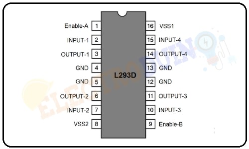
| Pin Number | Pin Name | Description |
| 1 | Enable-A |
Enable-A pin is used to control the speed of Motor A. If you connect this pin to +5 V, Then the motor will be enabled, then the Motor A rotates maximum speed. If we connect this pin to a PWM input of the microcontroller. In that way, we can control the speed of Motor A. If we connect this pin to Ground the Motor A will be disabled. |
| 2,7 | INPUT-1 & INPUT-2 | These pins are input pins of Motor A. These are used to control the rotating direction of Motor A. When one of them is HIGH and the other is LOW, Motor A will start rotating in a particular direction. If both the inputs are either HIGH or LOW the Motor A will stop. |
| 4, 5, 12, 13 | GND | GND is a ground pin. It needs to be connected to the power supply ground(negative). |
| 3, 6 | OUTPUT-1 & OUTPUT-2 | This Pin will provide the output for Motor A. |
| 8 | VSS2 | Connected to Power supply positive pin for running motors (4.5V to 36V) |
| 9 | Enable-B |
Enable-B pin is used to control the speed of Motor B. If you connect this pin to +5 V, Then the motor will be enabled, then the Motor B rotates maximum speed. If we connect this pin to a PWM input of the microcontroller. In that way, we can control the speed of Motor B. If we connect this pin to Ground the Motor B will be disabled. |
| 10, 15 | INPUT-3 & INPUT-4 | These pins are input pins of Motor B. These are used to control the rotating direction of Motor B. When one of them is HIGH and the other is LOW, Motor B will start rotating in a particular direction. If both the inputs are either HIGH or LOW the Motor B will stop. |
| 11, 14 | OUTPUT-3 & OUTPUT-4 | This Pin will provide the output for Motor B. |
| 16 | VSS1 | 5V supply for the functioning of the IC. |
How L293D Motor Driver IC Works
This IC uses two techniques for the control speed and rotation direction of the DC motors. These are H-Bridge – For controlling rotation direction and PWM – For controlling the speed.
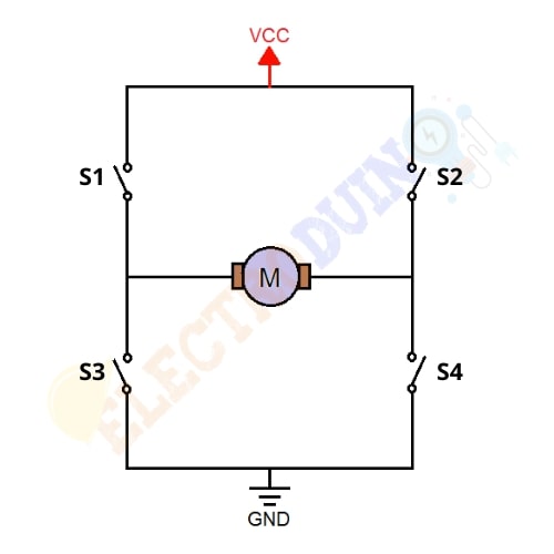
H-Bridge Techniques
L293D motor driver IC uses the H-Bridge technique to control the direction of rotation of a DC motor. In this technique, H-Bridge controlled DC motor rotating direction by changing the polarity of its input voltage.
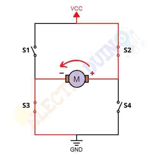
An H-Bridge circuit contains four switching elements, like transistors (BJT or MOSFET), with the motor at the center forming an H-like configuration.
We can change the direction of the current flow by activating two particular switches at the same time, this way we can change the rotation direction of the motor.
Case 1: When S1, S2, S3, and S4 all switches are open then no current goes to the Motor terminals. So, in this condition, the motor is not working.
Case 2: When the switch S1 and S4 are closed, then the motor left terminal is getting a positive (+) voltage and the motor right terminal is getting a negative(-) voltage. So, in this condition motor start rotating in a particular direction (clockwise).
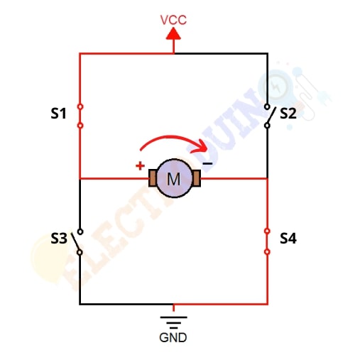
Case 3: When S2 and S3 switches are closed, then the right motor terminal is getting a positive (+) voltage and the left motor terminal is getting a negative (-) voltage. So, in this condition motor start rotating in a particular direction (anticlockwise).
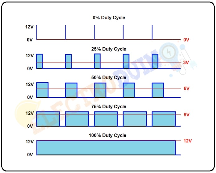
PWM (Pulse Width Modulation) Techniques
L298n motor driver IC uses the PWM technique to control the speed of rotation of a DC motor. In this technique, the speed of a DC motor can be controlled by changing its input voltage.
Pulse Width Modulation is a technique where the average value of the input voltage is adjusted by sending a series of ON-OFF pulses. The average voltage is proportional to the width of the pulses, these pulses known as Duty Cycle.
If the duty cycle higher, then the average voltage is applied to the DC motor (High Speed), and the lower the duty cycle, the less the average voltage being applied to the dc motor(Low Speed).
Motor Driver IC Specifications & Features
| Parameter | Value |
| IC Type | Available in 16-pin DIP, TSSOP, SOIC packages |
| IC Supply Voltage to VSS1(VSS) | 4.5V to 7V |
| Motor voltage VSS2 (Vs) | 4.5V to 36V |
| Maximum Continuous Motor Current | 600mA |
| Maximum Peak motor current | 1.2A |
| Transition time | 300ns (at 5Vand 24V) |
| Drives motor | Drives up to 2 motors (1 for each motor output terminal block) or One Stepper Motor |
| Motor Control | Speed and Direction control |
L293D Equivalent Dual Timer IC
LB1909MC, SN754410, ULN2003
Applications
- Control DC motors.
- Control stepping motors
- In Robotics
- driven High current LED
- Relay Driver module
Content Source: Introduction to L298N Motor Driver | How it’s work