What is RFID RC522 Module | How Does it Work
Hello friends! Welcome back to ElectroDuino. This blog is based on What is RFID RC522 Module | How Does it Work. Here we will discuss the What is RFID RC522 Module, Hardware Overview, Pin Diagram, Working Principle, Specification/Features, and Applications.
What is RFID RC522 Module

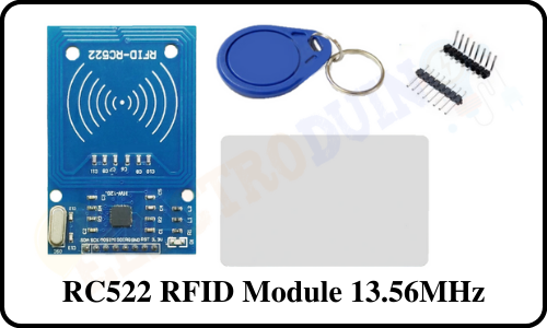
The RC522 RFID Reader/Writer Module (Transceiver) is based on a highly integrated reader/writer IC MFRC522 from NXP Company. It is used for contactless Multi-communication at 13.56 MHz. The RFID stands for Radio Frequency Identification. This module uses electromagnetic waves in radio frequency to transfer data (read/write). It can read/write all types of Transponders (RFID card tags and key fob tags) which haveing 1KB memory and compatible with 13.56 MHz frequency. This is a low-voltage, low-cost, small-sized module and It comes with SPI protocol which enables it to easily interface with almost any microcontroller like ATTiny, Arduino, ESP8266, Raspberry Pi, and other more advanced development boards.
Hardware Overview
In the market or online the RC522 RFID module comes as a kit set, which consists of the RC522 RFID Reader Module (transceiver), RFID Card Tag, Key Fob Tag, and 8 pin male headers.
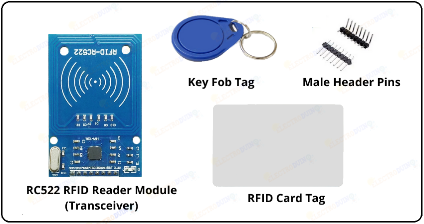
RC522 RFID Reader Module
The RC522 RFID Reader Module or Transceiver is a reader/writer device that is capable of reading/writing data from/to an RFID transponder. It consists of 3 key components, these are the MFRC522 IC, a 27.12 MHz Crystal Oscillator, and Antenna.
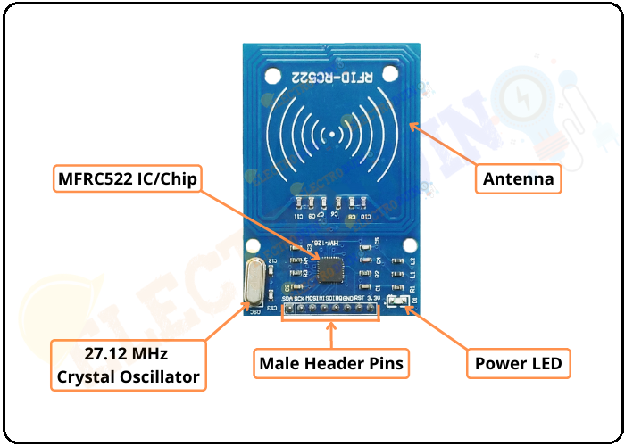
MFRC522 IC/Chip: The RC522 RFID Reader Module is based on MFRC522 IC/Chip. This is the high integrated RFID card reader IC/Chip designed by NXP Company, it works on non-contact 13.56mhz communication. It is low power consumption, low cost, and small size read and write chip. The MFRC522 IC supports various types of RFID Tags like MIFARE 1K, MIFARE 4K, MIFARE Mini, and other ISO / IEC 14443 standard protocol-based cards and tags. Also, it supports Mifare series higher speed contactless communication, duplex communication speed up to 424 kb/s. The MFRC522 IC operates at a 13.46 MHz frequency with an operating range of up to 50 mm depending on the antenna size and tuning. The MFRC522 IC supports SPI, UART, and I2C serial communication with the host (Microcontroller like Arduino).
27.12 MHz Crystal Oscillator: A 27.12 MHz quartz crystal is connected to the OSCIN and OSCOUT pin of the chip for the Internal oscillator. 13.56 MHz clock pulse derived from the 27.12MHz clock pulse of the 27.12 MHz quartz crystal oscillator divided by 2.
Antenna: An NFC Coil is embedded in the PCB of the module. This is an antenna that emits a 13.56 MHz high-frequency electromagnetic field. It supports 13.56 MHz passive components.
RFID Card and Key Fob Tags
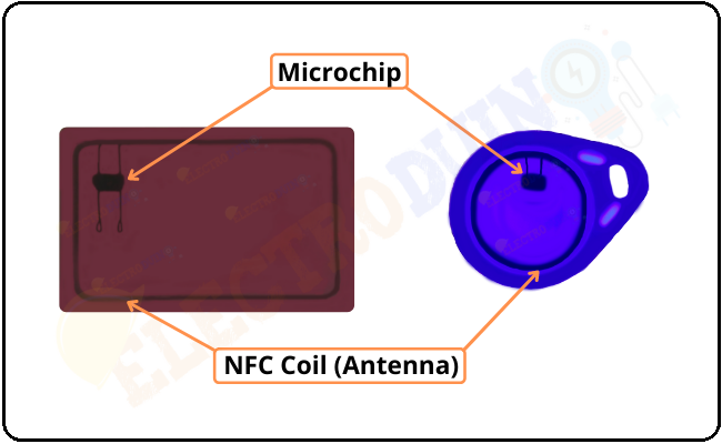
The RFID Card tag and Key fob tags (transponder) are passive devices, i.e. it doesn’t contain a power source (battery). These consist of a microchip and an NFC Coil (Antenna). The microchip is for the storage of the data, and the NFC Coil (Antenna) is for transmitting the data to the RFID reader module. The RC522 RFID Reader Module is compatible with MIFARE 1K tags. These tags have 1kB memory to store unique data.
RC522 RFID Module Pin Diagram/ Pin Configuration/ Pinout
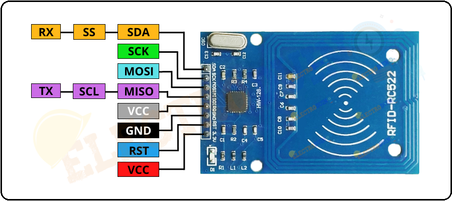
VCC: This is the power supply pin for the module. The module operates on the voltage range of from 2.5 to 3.3 volts. we can connect it to the 3.3V output pin of the microcontroller (Arduino).
RST: The reset pin is an input for Reset and power-down the module. When this pin goes low, the power-down is enabled, then this turns off all internal current sinks including the oscillator and the input pins of the module are disconnected from the outside world.
GND: This is the Ground pin of the module. we need to connect it to the ground pin of the microcontroller (Arduino).
IRQ: This is an interrupt pin that alerts the microcontroller to wake up the module when an RFID tag comes into its range. It helps the module to go into sleep mode to save power.
MISO / SCL / Tx: When the SPI interface is enabled This pin acts as Master-In-Slave-Out, When the I2C interface is enabled the pin acts as serial clock, and when the UART interface is enabled acts as serial data output.
MOSI: This is Master Out Slave In pin for SPI communication
SCK: This is Serial Clock pin. It accepts clock pulses provided by the SPI bus Master i.e. microcontroller (Arduino).
SS / SDA / RX: This pin acts as Serial input (SS) during SPI communication, SDA during I2C, and Rx during UART
How Does RFID RC522 Module Work
The RFID reader module or Transceiver uses electromagnetic waves in radio frequency to transfer data. The control unit and an antenna coil of the reader module generate a high-frequency electromagnetic field.
When an RFID tag or Transponder comes in the range of the electromagnetic field (detection range) of an RFID reader module (Transceiver). Due to mutual induction, a voltage is generated in the antenna coil of the tag, and this voltage work as a power supply for the microchip.
Now, the tag starts transmitting data serially and the reader read the tag information. This technique is known as load manipulation.
Specification/Features
- Operating Voltage: 2.5V~3.3V.
- Working current: 13 – 26mA at 3.3V
- Standby current: 10 – 13mA at 3.3V
- Sleep current: <80uA
- Peak current: <30mA
- Operating Frequency: 13.56MHz
- Compatible with ISO 14443A and MIFARE 1K cards and key fob tags.
- Supports ISO/IEC 14443A higher transfer speed communication: up to 848 KBd.
- Supports SPI bus speed: up to 10Mbit/s.
- Supports I2C-bus interface: In Fast mode Speed: up to 400 kBd, In High-speed mode: up to 3400 kBd
- RS232 Serial UART Speed: up to 1228.8 kBd, with voltage levels dependent on pin voltage supply.
- Typical Operating Range: up to 50 mm in Read/Write mode, it depends on the antenna size and tuning.
- Working temperature:-20 to 80 degree
- Storage temperature:-40 to 85 degree
- Humidity: Relevant Humidity 5%—95%
- Board Dimension:40mm × 60mm
Applications
- Automatic billing systems
- Access control systems
- Verification/Identification system
- Attendance systems
Download RFID Reader Module Chip MFRC522 Datasheet Pdf