

Four Way Traffic Light Controller Circuit using 555 Timer IC and CD4017
Hello friends! Welcome back to ElectroDuino. This blog is based on Four Way traffic light controller Circuit using 555 Timer IC and CD4017 counter IC. Here we will discuss Introduction to Four Way traffic light controller Circuit, Project Concept, Block Diagram, components required, circuit diagram, working principle.
Introduction
In modern times, every day the number of vehicles is increasing. We all have seen traffic lights, which placed at road intersections, pedestrian crossing, and other locations to control flows of traffic. These traffic lights are used to avoid traffic jams and accidents on roads. The traffic signal has three different color lights, which indicates three different messages for the drivers, Red for STOP, Yellow for WAIT, and Green for GO.
in this project, we will make a Four-Way traffic light controller Circuit using 555 Timer IC and CD4017 counter IC, which can help us to understand how a traffic light system works. This type of traffic light is placed at the center point of the four-way crossing.
Project Concept
The key components of this project are Potentiometer, Ne555 timer IC, CD4017 counter IC and LEDs. The NE555 IC works as an astable multivibrator to produce pulses. The time period of these pulses can be adjusted by the Potentiometer. It means the Potentiometer is used to change the shifting time of the Traffic light. Then the output pulse from the NE555 timer IC goes into the clock input of the CD4017 counter IC. Then the counter IC counts pulse and changes the output line (Q) logic into HIGH or LOW. We can obtain traffic signal light by connecting the proper color LED with the counter IC output pins. Here we will use 3 different color LEDs, 4 for each color.
Block Diagram of Four Way Traffic Light Controller

Components Required
| Components Name | Quantity |
| NE 555 Timer IC | 1 |
| CD4017 Decade Counter IC | 1 |
| 1K ohm Resistor | 1 |
| 220 ohm Resistor | 3 |
| 100KΩ Potentiometer | 1 |
| 10µF capacitor | 1 |
| 100µF capacitor | 1 |
| IN4007 Diodes | 8 |
| Red LED | 4 |
| Yellow LED | 4 |
| Green LED | 4 |
| 9v Power supply voltage | 1 |
| Slide Switch (SW1) | 1 |
| PCB Zero board | 1 |
| Connecting Wire | As required in the circuit diagram |
Tools Required
| Tools Name | Quantity |
| Soldering Iron | 1 |
| Soldering wire | 1 |
| Soldering flux | 1 |
| Soldering stand | 1 |
| Multimeter | 1 |
| Desoldering pump | 1 |
| Wirecutter | 1 |
Four Way Traffic Light Controller Circuit Diagram

Working Principle of Four Way Traffic Light Controller Circuit using 555 Timer IC and CD4017
Here the NE555 IC works as an astable multivibrator mode and produces pulses as output. We can change the time period of the output pulses by changing the value of R1, R2, and C1. Here we have replaced the R2 resistance with a potentiometer (VR1). So we can change the time period of the output pulses by rotating the potentiometer knob [Because the resistance (R2) value is change]. So, the 555 timer IC acts as a square wave generator and generated clock pulses. This input change is to change the shifting time of the Traffic light (LEDs).
Then the Clock pulse from the NE555 timer IC goes into the clock input of the CD4017 counter IC. Then the counter IC counts pulse and changes the output line (Q) logic into HIGH or LOW. For example, if the counter IC count is 2 then the Q1 pin of the counter will be high, and if 3 counts the pin Q2 will be high.
The 1N4007 diodes are used to prevent the shorting of counter outputs. For example, if the IC count is 2 then the Q1 will be high, but this time all other outputs will be Low. if we have not used the diodes, Q1 with positive voltage gets hardly pulled down to LOW by Q0, Q2, and Q3 as they will connect together. Then this short circuit takes place.
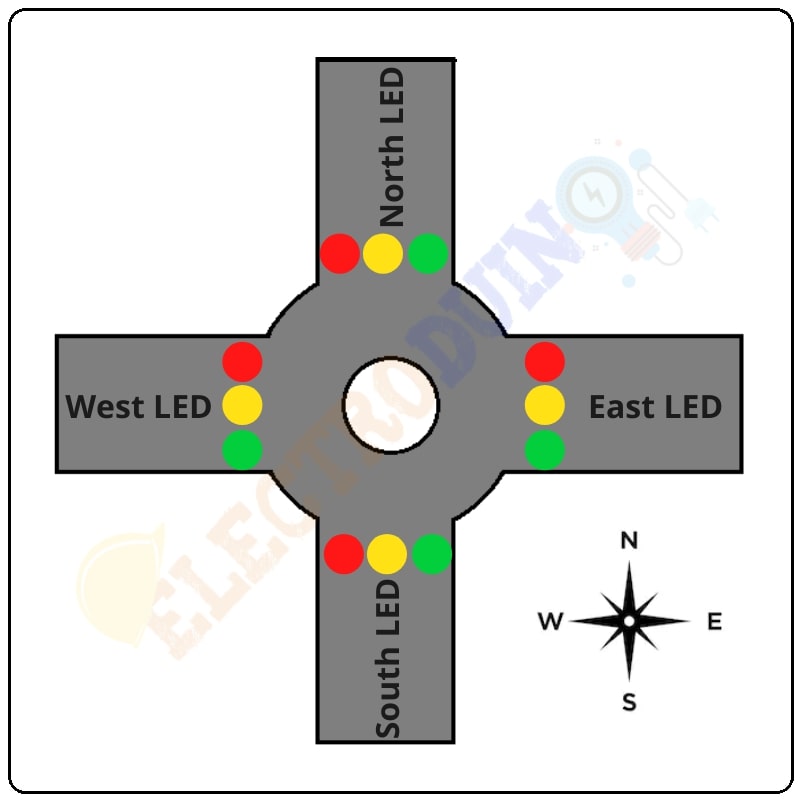
- When, the output of the Q0, Q1, Q2, Q3 pins goes high, then the GREEN LED on NORTH and SOUTH will be ON along with RED LED on EAST and WEST.
- When the output of the Q4 pin goes high, then the YELLOW LED on NORTH and SOUTH will be ON along with RED LED on EAST and WEST.
- When, the output of the Q5, Q6, Q7, Q7 pins goes high, then the GREEN LED on EAST and WEST will be ON along with RED LED on NORTH and SOUTH.
- When the output of the Q9 pin goes high, then the YELLOW LED on EAST and WEST will be ON along with RED LED on NORTH and SOUTH.


