LM393 IC-based Automatic Night Light Circuit
Hello friends! Welcome back to ElectroDuino. This blog is base on the LM393 IC-based Automatic Night Light Circuit. Here we will discuss project Introduction to Automatic Night Light Circuit, Block diagram, Component Required, Component Description, Circuit Design, Circuit Wiring, Working principle and output Result
Introduction
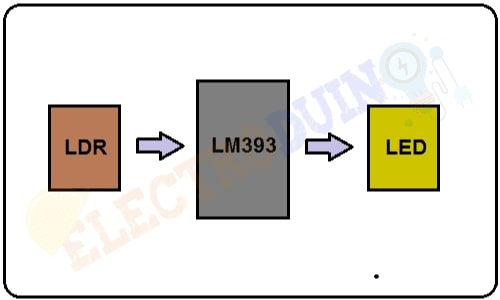
LM393 IC-based Automatic Night Light Circuit is a very simple project which can automatically control Light on/off by detecting light and dark. In this project mainly consists of an LM393 Comparator IC and an LDR. The LDR detects light and dark and the LM393 processes the LDR data and provide output. The circuit works like this, when LDR detects dark then it turns on the light and when LDR detects light then it turns off the light.
Automatic Night Light Circuit Block diagram
Component Required
| Components Name | Quantity |
| LM393 Comparator IC | 1 |
| LDR (Light Dependent Resistor) or Photoresistor | 1 |
| 10K Potentiometer | 1 |
| 33KΩ Resistor | 1 |
| 330Ω Resistor | 1 |
| LED | 1 |
| 5v Power Supply | 1 |
| Connecting wire | As required in the circuit diagram |
Tools Required
| Tools Name | Quantity |
| Soldering Iron | 1 |
| Soldering wire | 1 |
| Soldering flux | 1 |
| Soldering stand | 1 |
| Multimeter | 1 |
| Desoldering pump | 1 |
| Wirecutter | 1 |
Component Description
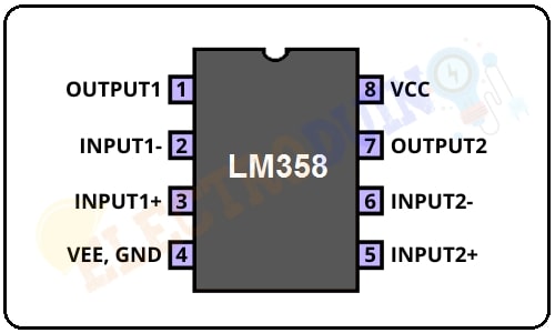
LM393 Comparator IC
The LM393 integrated circuit (IC) is a dual differential comparator, it consists of two inbuilt operational amplifiers. Each comparator accepts 2 inputs for comparison. The comparator compares these two input voltages and measure which input voltage is the larger, then it provides output. These ICs can perform different tasks using a single power supply. Also, it can be work perfectly by the split power supply sources.
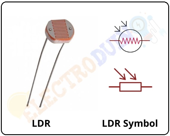
LDR (Light Dependent Resistor)
The LDR or Light Dependent Resistor is a variable resistor. It is also known as a photoresistor. These LDR, Light Dependent Resistor, or Photoresistor works on the principle of “Photo Conductivity”. The LDR resistance is change depends on the light intensity falls on the LDR surface. When light falls on the surface of the LDR then the resistance of the LDR decreases and increases the conductance of the element. When no light falls on the surface of the LDR then the resistance of the LDR is high and decreases the conductance of the element.
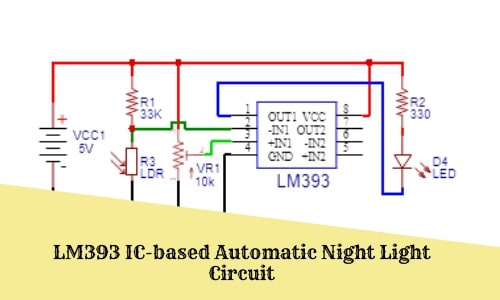
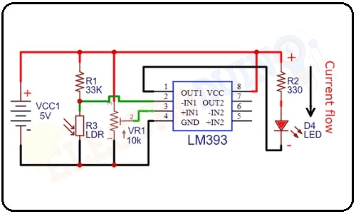
Circuit Design of LM393 IC-based Automatic Night Light Circuit
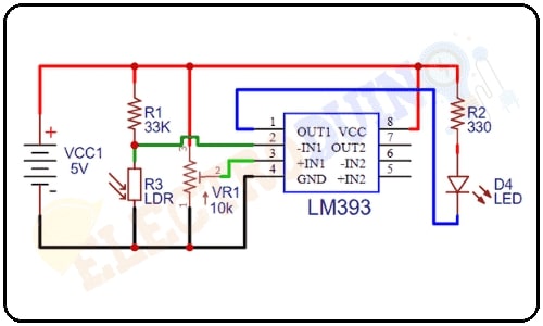
Circuit Wiring
The LM393 IC Vcc pin is connected to the positive terminal of 5v power supply and the IC GND pin is connected to the negative terminal of 5v power supply.
The LDR one terminal is connected to the positive terminal of 5v power supply through the 33k resistor and another terminal is connected to the negative terminal of 5v power supply. This makes a voltage divider circuit. The junction point of the LDR and the resistor is connected to Inverting 1 input (pin 2) of IC.
The Potentiometer one pin is connected to the positive terminal of 5v power supply and another pin is connected to the negative terminal of 5v power supply. The potentiometer output pin is connected to the Non-Inverting 1 input(Pin3) of the IC.
The LED positive terminal is connected to the positive terminal of the 5v power supply through the 330-ohm resistor and the negative terminal is connected to the Output 1 (Pin 1) of the IC.
Working of LM393 IC-based Automatic Night Light Circuit
First of all, we need to calibrate the Non-Inverting 1 input voltage by rotating the Potentiometer and set a referral voltage at Non-Inverting 1 input. Potentiometer calibrates like this, during light conditions the LED is off and the LED is on during dark conditions.
Then the lm393 comparator IC compares this reference voltage with the voltage produced from the voltage divider between the LDR or photoresistor and the 33KΩ resistor.
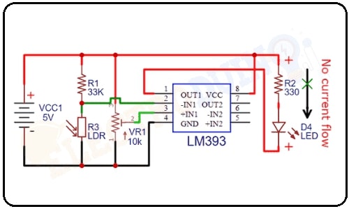
When light falls on the photoresistor surface, its resistance decrease below 30KΩ. So, most of the voltage gets allocated to the 33KΩ resistor and a small voltage goes across the LDR. So, the voltage divider produces a small voltage. Then, this small voltage goes to the Inverting 1 input (pin 2) of IC, which is less than the reference voltage. So, the IC output 1 is High, it means the output voltage is equal to the positive supply voltage (5v Vcc), and there is no current flow across the load because there is no potential difference. So the LED is turned OFF.
When no light falls on the photoresistor surface, it has very high resistance. So, most of the voltage gets allocated to the LDR. So, the voltage divider produces a High voltage. Then, this High voltage goes to the Inverting 1 input (pin 2) of IC, which is greater than the reference voltage. So, the IC output 1 is Low, it means the output voltage is equal to the Ground of supply voltage (0v Vcc), and the current flow across the load from positive supply to groud because there is a potential difference. So the LED is turned ON.
Output Result
When LDR detects dark then it turns on the LED and when LDR detects light then it turns off the LED.