Arduino Home Automation System using GSM SIM800
Hello friends! Welcome back to ElectroDuino. This blog is based on SMS Based Arduino Home Automation System using SIM800 GSM. Here we will discuss the Introduction to Arduino Home Automation System using GSM SIM800, Project Concept, Block Diagram, Components Required, Circuit Diagram, working principle, and Arduino code.
Introduction
In these modern days, everyone has a Phone (Normal GSM phone or smartphone). Normally we are using these phones to communicate with other people by calling, and SMS. In this project, we will use SMS (messages) technology to control home Appliances Wirelessly. So here we will make GSM SIM800 and Arduino based home automation system which controls by SMS. Using this system we can turn ON and turn OFF AC home appliances/devices by sending messages from a phone. This system works on GSM communication, so we can control it from anywhere in the world if then the mobile network is available. It can be controlled by a normal GSM phone or a smartphone.
Project Concept/Overview
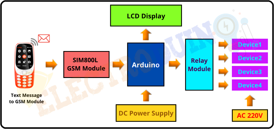
This is a very simple home automation project, few components are needed to build this project. The key components of this project are SIM800L GSM Module, Arduino board, Relay Module, LCD Display, Micro SIM Card, and a phone. In this project, The GSM module acts as a means of communication between the phone and the Arduino. We need to insert a Micro SIM Card into the GSM module. When we send a particular SMS/message (this SMS/message is already defined in Arduino code) to the Number of the Micro SIM Card. Then the GSM module receives that message and sends it to the Arduino. The Arduino board is the main controller of this system, it decodes this massage from the GSM and compares the massage to the pre-defined SMS/messages. If the SMS/message is matched, then Arduino sends a command to the relay module to control home appliances/devices. The relay is an electronic switch that controls AC appliances/devices. Here we have used 4 channel Relay module to control 4 devices. The LCD display module is used to display the device status, it is ON or OFF.
Block Diagram of SMS Based Arduino Home Automation System
Components Required
| Components Name | Quantity |
| Arduino NANO | 1 |
| GSM SIM800L Module | 1 |
| 16×2 LCD Module | 1 |
| 4 Channel Relay Module | 1 |
| AC Bulb with Holder and Wire | 4 |
| 9V 1 Amp Adapter (DC Power supply) | 1 |
| Cell phone | 1 |
| PCB board | 1 |
| Connecting wires | As required in the circuit diagram |
| 220V AC Power supply |
Tools Required
| Tools Name | Quantity |
| Soldering Iron | 1 |
| Soldering wire | 1 |
| Soldering flux | 1 |
| Soldering stand | 1 |
| Multimeter | 1 |
| Desoldering pump | 1 |
| Wirecutter | 1 |
Software Required
 | Arduino IDE (Integrated Development Environment) |
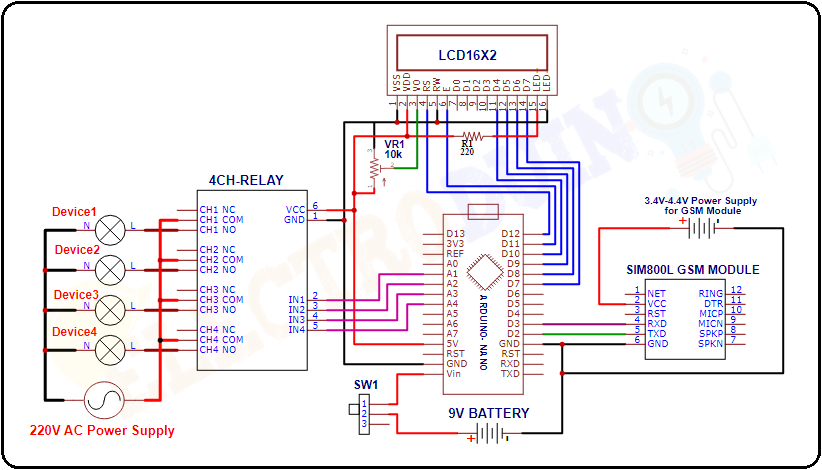
Circuit Diagram/Schematic of SMS Based Arduino Home Automation System
Commands are used in Arduino Code
First of all, we need to select 8 commands messages. These commands are defined in Arduino code. When we send a command message from our phone to the GSM module, then Arduino detects this message and sends the command to the relay module. Here we are using 8 commands to control 4 relays of the relay module, which means two commands for each relay. Here we have used a prefix in command that is “#”, which is used to identify that the main command is coming next to it and the “*” prefix used at the end of the command, which indicates the message has been ended. For example, the “#D1 ON*” SMS/message is used to turn on the Relay1, and the “#D1 OFF*” SMS/message is used to turn off the Relay1. The List of the SMS/messages and their use is described below
| SL.NO | SMS from Phone | Operation |
| 1 | #D1 ON* | Turn ON the Relay1 |
| 2 | #D1 OFF* | Turn OFF the Relay1 |
| 3 | #D2 ON* | Turn ON the Relay2 |
| 4 | #D2 OFF* | Turn OFF the Relay2 |
| 5 | #D3 ON* | Turn ON the Relay3 |
| 6 | #D3 OFF* | Turn OFF the Relay3 |
| 7 | #D4 ON* | Turn ON the Relay4 |
| 8 | #D4 OFF* | Turn OFF the Relay4 |
| 9 | #All ON* | Turn ON All Relay |
| 10 | #All OFF* | Turn OFF All Relay |
Arduino Code
#include<SoftwareSerial.h>  //Include Library for GSM Module
#include<LiquidCrystal.h>   //Include Library for LCD Display Module
SoftwareSerial mySerial(3,2);  // (Rx,Tx  > Tx,Rx)
LiquidCrystal lcd(12, 11, 10, 9, 8, 7);// Select Arduino pins for LCD Display

char incomingByte;
String inputString;
int relay1 = A1; // Output for Relay Control
int relay2 = A2; // Output for Relay Control
int relay3 = A3; // Output for Relay Control
int relay4 = A4; // Output for Relay Control

   void setup()
    {
      lcd.begin(16,2);

      pinMode(relay1, OUTPUT);
      pinMode(relay2, OUTPUT);
      pinMode(relay3, OUTPUT);
      pinMode(relay4, OUTPUT);

      lcd.setCursor(0,0);
      lcd.print("GSM Control Home");
      lcd.setCursor(0,1);
      lcd.print("   Automaton    ");
      delay(2000);
      lcd.clear();
      lcd.print("ElectroDuino.com");
      delay(1000);
      lcd.setCursor(0,1);
      lcd.print("System Ready");

      digitalWrite(relay1, HIGH); // Relay1 is initially off
      digitalWrite(relay2, HIGH); // Relay2 is initially off
      digitalWrite(relay3, HIGH); // Relay3 is initially off
      digitalWrite(relay4, HIGH); // Relay3 is initially off

      lcd.clear();
      lcd.setCursor(0,0);
      lcd.print(" D1  D2  D3  D4 ");
      lcd.setCursor(0,1);
      lcd.print("OFF OFF OFF OFF");

      Serial.begin(9600);   // Set Baud rate for serial communication
      mySerial.begin(9600); // Sim Baud rate

      while(!mySerial.available())
       {
        mySerial.println("AT");
        delay(1000);
        Serial.println("Connecting...");
       }
      Serial.println("Connected!");
      mySerial.println("AT+CMGF=1");  //Set SMS to Text Mode
      delay(1000);
      mySerial.println("AT+CNMI=1,2,0,0,0");  //Procedure to handle newly arrived messages(command name in text: new message indications to TE)
      delay(1000);
      mySerial.println("AT+CMGL=\"REC UNREAD\""); // Read Unread Messages
    }

   void loop()
    {
     if(mySerial.available())
     {
      delay(100);
      // Serial Buffer
      while(mySerial.available())
       {
        incomingByte = mySerial.read();
        inputString += incomingByte;
       }
      delay(10);

      Serial.println(inputString);
      inputString.toUpperCase(); // Uppercase the Received Message

        //turn RELAY1 ON or OFF
      if (inputString.indexOf("#D1 ON*") > -1)
       {
        digitalWrite(relay1, LOW);
        lcd.setCursor(0,1);
        lcd.print(" ON");
        delay(200);
       }

      else if (inputString.indexOf("#D1 OFF*") > -1)
       {
        digitalWrite(relay1, HIGH);
        lcd.setCursor(0,1);
        lcd.print("OFF ");
        delay(200);
       }
//turn RELAY2 ON or OFF
      else if (inputString.indexOf("#D2 ON*") > -1)
       {
        digitalWrite(relay2, LOW);
        lcd.setCursor(4,1);
        lcd.print(" ON");
        delay(200);
       }
      else if (inputString.indexOf("#D2 OFF*") > -1)
       {
        digitalWrite(relay2, HIGH);
        lcd.setCursor(4,1);
        lcd.print("OFF ");
        delay(200);
       }
//turn RELAY3 ON or OFF
      else if (inputString.indexOf("D3 ON*") > -1)
       {
        digitalWrite(relay3, LOW);
        lcd.setCursor(8,1);
        lcd.print(" ON");
        delay(200);
       }
      else if (inputString.indexOf("#D3 OFF*") > -1)
       {
        digitalWrite(relay3, HIGH);
        lcd.setCursor(8,1);
        lcd.print("OFF ");
        delay(200);
       }

//turn RELAY1 ON or OFF
      else if (inputString.indexOf("#D4 ON*") > -1)
       {
        digitalWrite(relay4, LOW);
        lcd.setCursor(12,1);
        lcd.print(" ON");
        delay(200);
       }
      else if (inputString.indexOf("#D4 OFF*") > -1)
       {
        digitalWrite(relay4, HIGH);
        lcd.setCursor(12,1);
        lcd.print("OFF ");
        delay(200);
       }

  //turn All RELAY ON or OFF
      else if (inputString.indexOf("#ALL ON*") > -1)
       {
        digitalWrite(relay1, LOW);
        digitalWrite(relay2, LOW);
        digitalWrite(relay3, LOW);
        digitalWrite(relay4, LOW);
        lcd.setCursor(0,1);
        lcd.print("ON  ON  ON  ON ");
        delay(200);
        digitalWrite(relay1, HIGH);
        digitalWrite(relay2, HIGH);
        digitalWrite(relay3, HIGH);
        digitalWrite(relay4, HIGH);
        lcd.setCursor(0,1);
        lcd.print("OFF OFF OFF OFF");
        delay(200);
       }
      else if (inputString.indexOf("#ALL OFF*") > -1)
       {
        digitalWrite(relay1, HIGH);
        digitalWrite(relay2, HIGH);
        digitalWrite(relay3, HIGH);
        digitalWrite(relay4, HIGH);
        lcd.setCursor(0,1);
        lcd.print("OFF OFF OFF OFF");
        delay(200);
       }
        delay(50);

        //Delete Messages & Save Memory
      if (inputString.indexOf("OK") == -1)
      {
       mySerial.println("AT+CMGDA=\"DEL ALL\"");
       delay(1000);}
       inputString = "";
      }
}