
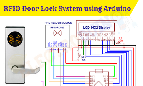
RFID Door Lock System using Arduino and RFID Module
Hello friends! Welcome back to ElectroDuino. This blog is based on RFID Door Lock System using Arduino. Here we will discuss Introduction to RFID Door Lock System using Arduino, Project Concept, Block Diagram, Components Required, Circuit Diagram, working principle, and Arduino code.
Introduction
In the previous age, a normal Lock and key are used to lock the door and gate. But in this modern age, some houses, hotels, offices, and other places are using Electronic door locks systems, these are basically keyless door locks i.e don’t need a key to unlock the door. Several types of access control systems are used in electronic door locks to access the door. The most used access control systems are PIN/Password (Personal Identification Number), fingerprint, and RFID based Electronic door locks systems.
In this project tutorial, we’ll learn how to make RFID based Electronic door locks systems using Arduino and RC522 RFID Module. In this system, you need a particular card or key tag and put it in front of the RFID door locks system box (RFID Reader) to unlock the door. If you put the wrong card or key tag in front of the RFID door locks system box (RFID Reader) then the door would not unlock. This system is also known as the card door lock system or key card door lock system.
Project Concept/Overview
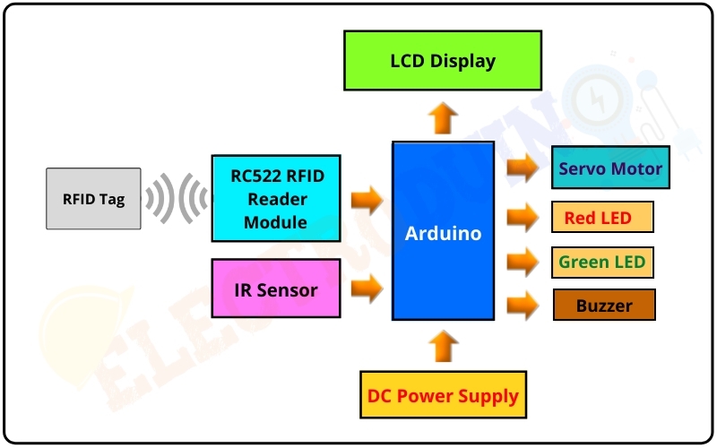
The RFID Door Lock System is constructed using 4 major components these are Arduino, RFID Redder Module, RFID Card or Key Fob Tag, IR Sensor, Servo Motor, and LCD Display. Here I’ll use Arduino Nano as the main microcontroller that controls the whole system. You can use any other type of Arduino board like Arduino Uno or Mega. The RFID Redder Module is used to read the Card or Key Tag value and send the value to the Arduino. Then the Arduino matches this value with the pre-defined value in the code. If this value is matched then the microcontroller sends a command to the servo motor to unlock the door. The servo motor is used to control the lock mechanism. The IR sensor is used to check whether the door is open or closed. LCD display shows the RFID value reading status (Card correct or wrong) and the door status (open/close). LEDs and buzzer are used as door status (open/close) indicators.
Block Diagram of RFID Door Lock System using Arduino
Components Required
| Components Name | Quantity |
| Arduino NANO | 1 |
| RC522 RFID Module | 1 |
| RFID Card or Key Fob Tag | 1 |
| IR Sensor Module | 1 |
| 16×2 LCD Display Module | 1 |
| Sg-90 Servo Motor | 1 |
| 220 ohm Resistor (R1, R2, R3) | 3 |
| 10K ohm Potentiometer (VR1) | 1 |
| Red LED | 1 |
| Green LED | 1 |
| 5v Buzzer | 1 |
| 9v Power Supply | 1 |
| Rocker Switch | 1 |
| PCB board | 1 |
| Connecting wires | As required in the circuit diagram |
Tools Required
| Tools Name | Quantity |
| Soldering Iron | 1 |
| Soldering wire | 1 |
| Soldering flux | 1 |
| Soldering stand | 1 |
| Multimeter | 1 |
| Desoldering pump | 1 |
| Wirecutter | 1 |
Software Required

|
Arduino IDE (Integrated Development Environment) |
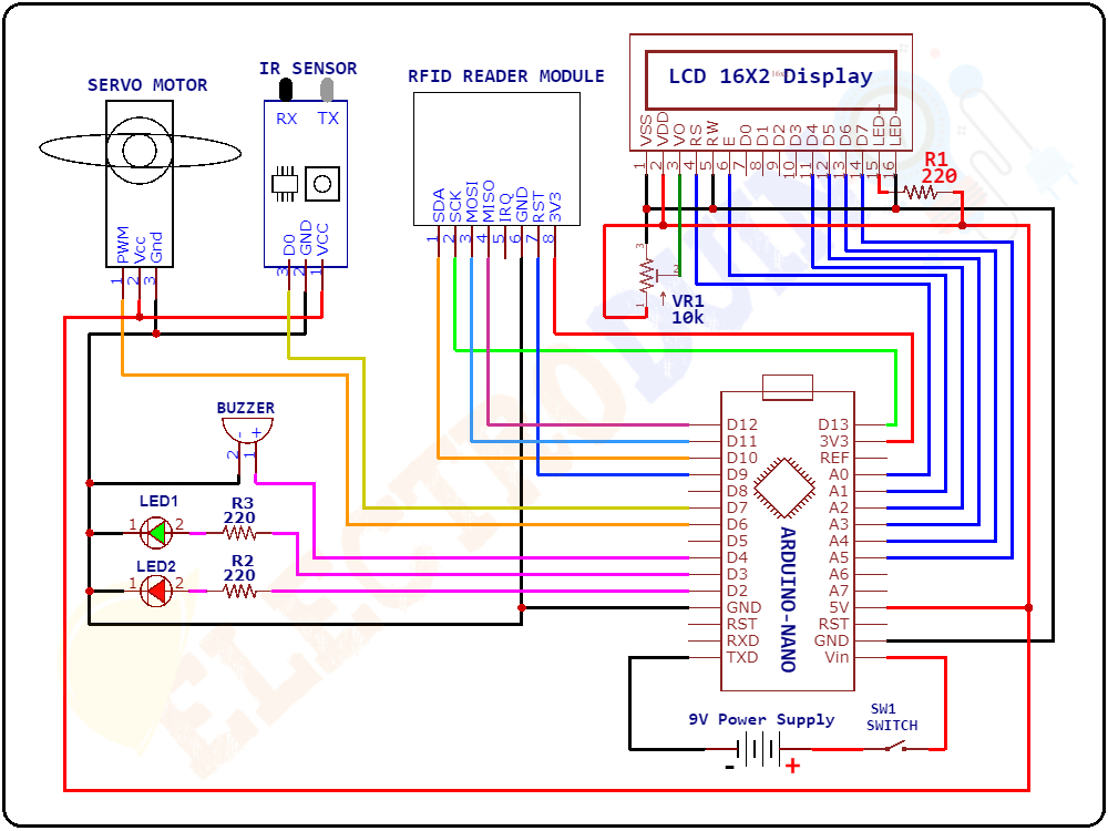
Circuit Diagram/Schematic of RFID Door Lock System using Arduino
Working Principle
Initially, the IR sensor module checks whether the door is open or closed. When the door is open the IR sensor produces High (1) output value from the output pin. The Arduino reads this value and understands the door is open, then sends a command to the servo motor to pull back the barrel handle of the sliding lock to unlock the door. This time the LCD display screen shows the message “Door is Open! Close The Door”, and the Red LED starts blinking and the buzzer generates the “Beep Beep” sound. In this condition, the RFID Reader Module does not read the card and key fob tags.
When the door is closed the IR sensor produces Low (0) output value from the output pin. Again the Arduino reads this value and understands the door is closed, then sends a command to the servo motor to push the barrel handle of the sliding lock forward to lock the door. This time the LCD display screen shows the message “Welcome – Scan Your Card>>”, and the Red LED is turned on. In this condition, the RFID Reader Module is Ready to read the card and key fob tags.
When an RFID Card/tag comes in the range of the RFID Reader Module (transceiver), it is scanning the Card/tag and reads the value. Then Arduino Nano board reads this value from the RFID Reader and matches this value with the pre-defined value in the code. Already we have saved the value of the Card/tag in the code.
If the Card/tag value is matched, then the Arduino produces PWM output from Pin 6 to activate the servo motor. Now the servo motor will pull back the barrel handle of the sliding lock to unlock the door. For a few seconds, the LCD display screen shows the message “Welcome, Door is Open”, and the Green LED starts blinking and the buzzer generates the “Beep Beep” sound.
- After this time if the door is not closed then the LCD display screen shows the message “Door is Open! Close The Door”, and the Red LED starts blinking and the buzzer generates the “Beep Beep” sound.
- If the door is closed during this time period, then the servo motor pushes the barrel handle of the sliding lock forward to lock the door. Now the system is ready to read the cards again.
If the Card/tag value does not match, then the Arduino doesn’t activate the servo motor. So the door will still be locked. The LCD display screen shows two messages “Wrong Card, Access Denied! ” then “Please, Try Again!”, Try Again”. Now the Red LED and buzzer will turn ON.
Arduino Code of RFID Door Lock System using Arduino
 /* RFID Door Lock System using Arduino and RFID Module
    www.Electroduino.com
 */

 //Include library
 #include <SPI.h>
 #include <MFRC522.h>
 #include <LiquidCrystal.h>
 #include <Servo.h>

 #define RST_PIN 9 // Define RST pin of RFID Connnected to Digital Pin 9
 #define SS_PIN 10 // Define RST pin of RFID Connnected to Digital Pin 10

 #define Sensor_Pin 7 // Define IR Sensor pin Connnected to Digital Pin 7

 #define Red_LED 2   // Define Red LED Connnected to Digital Pin 2
 #define Green_LED 3 // Define Green LED Connnected to Digital Pin 3
 #define Buzzer 4    // Define Buzzer pin Connnected to Digital Pin 4

 byte readCard[4];
 //Unique ID of RFID Tag, which you want to give access.
 String MasterTag = "A9591AB4";  // REPLACE this Tag ID with your Tag ID!!!
 String tagID = "";

 // Create instances
 MFRC522 mfrc522(SS_PIN, RST_PIN);
 LiquidCrystal lcd(A0, A1, A2, A3, A4, A5); // Define LCD Display pin Connnected to Arduino Pin
 Servo myServo; // Servo motor

 void setup()
  {
   // Initiating
   SPI.begin(); // SPI bus
   mfrc522.PCD_Init(); // MFRC522
   lcd.begin(16, 2); // //Initialise the LCD to 16x2 Character Format
   Serial.begin(9600); //open the serial port at 9600 baudrate.

   myServo.attach(6);  // declare Servo Connnected to Digital Pin 6

   //Set Components pin modes
   pinMode(Sensor_Pin,INPUT);
   pinMode(Red_LED, OUTPUT);
   pinMode(Green_LED, OUTPUT);
   pinMode(Buzzer, OUTPUT);

   myServo.write(10); // Initial lock position of the servo motor

   digitalWrite(Red_LED, HIGH);    // Red LED on
   digitalWrite(Green_LED, LOW); // Green LED off
   digitalWrite(Buzzer, LOW);    // Buzzer off

   //Print beginning message on LCD Display
   lcd.setCursor(0,0);
   lcd.print("ELECTRODUINO.COM");
   lcd.setCursor(0, 1);
   lcd.print(" RFID DOOR LOCK ");
   delay(2000);

   digitalWrite(Buzzer, HIGH);// Buzzer on
   delay(50);
   digitalWrite(Buzzer, LOW);// Buzzer off

   printNormalModeMessage(); // print Normal Mode Message on LCD Display
  }

 void loop()
  {
    int sensorValue = digitalRead(Sensor_Pin); // Read IR Sensor Output
    Serial.print (sensorValue); // IR Sensor Output on Serial Monitor

    // If Door is Closed
    if (sensorValue == 0)
     {
       myServo.write(10);        // Initial lock position of the servo motor
       printNormalModeMessage(); // print Normal Mode Message on LCD Display
       digitalWrite(Red_LED, HIGH);  // Red LED on
       digitalWrite(Green_LED, LOW); // Green LED off

       //Wait until new tag is available
       while (getID())
        {
         // If RFID Card or Key fob tag is Correct
         if (tagID == MasterTag)
          {
            myServo.write(170); // // Initial unlock position of the servo motor

            //Print message on LCD Display
            lcd.clear();
            lcd.setCursor(0,0);
            lcd.print("     Welcome    ");
            lcd.setCursor(0,1);
            lcd.print("  Door is Open  ");

            Green_LED_Blink(); // Green LED & Buzzer function
            digitalWrite(Red_LED, LOW); // Red LED off
            digitalWrite(Buzzer, LOW);  // Buzzer off
          }
         // If RFID Card or Key fob tag is Wrong
         if (tagID != MasterTag)
          {
            //Print message on LCD Display
            lcd.clear();
            lcd.setCursor(0,0);
            lcd.print("   Wrong Card   ");
            lcd.setCursor(0,1);
            lcd.print("  Access Denied! ");
            delay(2000);

            Red_LED_Blink2();// Red LED & Buzzer function2

            //Print message on LCD Display
            lcd.clear();
            lcd.setCursor(0,0);
            lcd.print("     Please     ");
            lcd.setCursor(0,1);
            lcd.print("   Try Again!   ");
            delay(2000);

            digitalWrite(Green_LED, LOW); // Green LED off
            digitalWrite(Buzzer, LOW);    // Buzzer off
            printNormalModeMessage();     // print Normal Mode Message on LCD Display
          }
        }
     }

    // If door is open...
    else
     {
      myServo.write(170); // // Initial unlock position of the servo motor

      //Print message on LCD Display
      lcd.clear();
      lcd.setCursor(0, 0);
      lcd.print("  Door is Open! ");
      lcd.setCursor(0, 1);
      lcd.print(" Close The Door ");

      Red_LED_Blink1(); // Red LED & Buzzer function2
     }
  }


  //Read new tag if available
  boolean getID()
   {
    // Getting ready for Reading PICCs
    if ( ! mfrc522.PICC_IsNewCardPresent()) { //If a new PICC placed to RFID reader continue
    return false;
    }
    if ( ! mfrc522.PICC_ReadCardSerial()) { //Since a PICC placed get Serial and continue
    return false;
    }
    tagID = "";
    for ( uint8_t i = 0; i < 4; i++) { // The MIFARE PICCs that we use have 4 byte UID
    //readCard[i] = mfrc522.uid.uidByte[i];
    tagID.concat(String(mfrc522.uid.uidByte[i], HEX)); // Adds the 4 bytes in a single String variable
    }
    tagID.toUpperCase();
    mfrc522.PICC_HaltA(); // Stop reading
    return true;
   }
 // print Normal Mode Message on LCD Display Function
 void printNormalModeMessage()
  {
   lcd.clear();
   lcd.setCursor(0,0);
   lcd.print("    Welcome   ");
   lcd.setCursor(0, 1);
   lcd.print("Scan Your Card>>");
  }

 // Red LED & Buzzer function1
 void Red_LED_Blink1()
  {
   for( int i = 0; i < 2; i = i +1 )
    {
     digitalWrite(Red_LED, HIGH); // Red LED on
     digitalWrite(Buzzer, HIGH);  // Buzzer on
     delay(700);
     digitalWrite(Red_LED, LOW); // Red LED off
     digitalWrite(Buzzer, LOW);  // Buzzer off
     delay(700);
    // We can adjust the delay time accordingly
    }
  }

 // Red LED & Buzzer function2
 void Red_LED_Blink2()
  {
   for( int i = 0; i < 5; i = i +1 )
    {
     digitalWrite(Red_LED, HIGH); // Red LED on
     digitalWrite(Buzzer, HIGH);  // Buzzer on
     delay(100);
     digitalWrite(Red_LED, LOW); // Red LED off
     digitalWrite(Buzzer, LOW);  // Buzzer off
     delay(100);
     // We can adjust the delay time accordingly
    }
  }

 // Green LED & Buzzer function
 void Green_LED_Blink()
  {
   for( int i = 0; i < 15; i = i +1 )
    {
     digitalWrite(Green_LED, HIGH); // Green LED on
     digitalWrite(Buzzer, HIGH);    // Buzzer on
     delay(150);
     digitalWrite(Green_LED, LOW); // Green LED off
     digitalWrite(Buzzer, LOW);    // Buzzer off
     delay(150);
     // We can adjust the delay time accordingly
    }
  }


