IR Sensor Module | How IR Sensor Module Works
Hello friends! Welcome back to ElectroDuino. This blog is based on, IR Sensor Module | How IR Sensor Module Works | How to make an IR Sensor Module. Here we will discuss Introduction to IR Sensor Module or Infrared Sensor(IR), Pin Diagram/Pinout, Hardware Overview, IR Sensor Module Circuit Diagram, Working Principle, Specifications, and applications.
Introduction
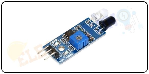
The IR Sensor Module or infrared (IR) sensor is a basic and most popular sensor in electronics. It is used in wireless technology like remote controlling functions and detection of surrounding objects/ obstacles. IR sensors mainly consist of an Infrared(IR) LED and a Photodiode, this pair is generally called IR pair. An IR LED is a special purpose LED, it is can emitting infrared rays ranging from 700 nm to 1 mm wavelength. These types of rays are invisible to our eyes. In contrast, a photodiode or IR Receiver LED detects the infrared rays.
IR Sensor Module Pin Diagram/Pinout
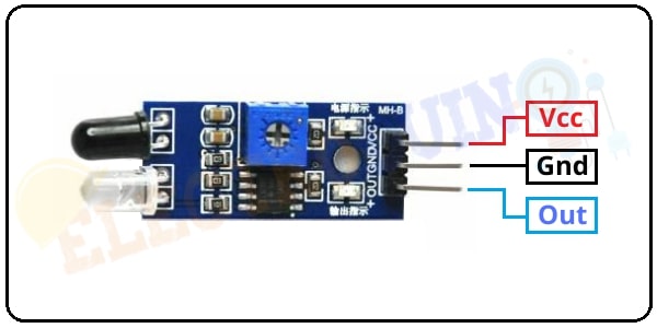
| Pin No | Pin Name | Description |
|
1 |
VCC |
+5 v power supply |
|
2 |
GND |
Ground (-) power supply |
|
3 |
OUT |
Digital Output |
| How to use the IR sensor with Arduino: Interfacing IR sensor with Arduino. |
IR Sensor Module Hardware Overview

The IR sensor module consists mainly of the 1. IR Transmitter, 2. Photodiode Receiver, 3. LM393 Comparators IC, 4. Variable Resistor (Trim pot), 5. Power LED, 6. output LED.
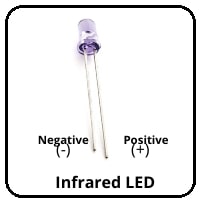
1. Infrared LED or IR Transmitter:
An IR LED is a specially designed light-emitting diode (LED), it’s emitting infrared rays. Infrared rays wavelength ranging is from 700 nm to 1 mm. Normally an IR LED looks like a normal LED. It has two terminals, the longer one is Positive and the smaller one is negative. When IR LED operated at a power supply, it starts emitting infrared rays.
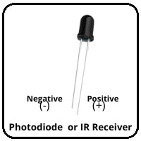
2. Photodiode Receiver or IR Receiver:
Normally IR receivers are photodiode. It is a semiconductor which has a P-N junction. A photodiode is capable to detect infrared rays. It’s operated in Reverse Bias. The photodiode has very High resistance in the absence of infrared rays and becomes low when infrared rays fall on it. Also, It has two terminals, the longer one is Positive and the smaller one is negative.
4. Variable Resistor (Trim pot)
IR sensor has an onboard variable resistor(potentiometer). This variable resistor is a 10k preset. It is used to set the range of operation. Rotate the preset knob to adjust the detection distance, the effective operation range 2-10 cm. If the preset knob rotated clockwise, the detection range will be increased. If it rotated counterclockwise, the detection range will be decreased.

5. Power LED:
This onboard LED indicates the IR Sensor power supply is ON or OFF. When we turn on the IR Sensor power supply this RED LED is also turn on.
6. Output LED:
When infrared reflected back to the IR receiver and the sensor detects an obstacle, the green LED lights up. So, the Green LED use to indicate the sensor senses an obstacle.
How to make an IR Sensor Module
Components Required
| Components Name | Quantity |
| IC: LM358 or LM393 (You can choose any one of these ICs) | 1 |
| IR (Infrared) LED (IR-TX) | 1 |
| Photodiode (IR-RX) | 1 |
| 1K Resistor (R1, R4) | 2 |
| 100 ohm Resistor (R2) |
1 |
| 10K Resistor (R3) | 1 |
| 10K Potentiometer (VR1) | 1 |
| 0.1 uF Ceramic Capacitor (C1, C2) | 2 |
| Red LED (D1) | 1 |
| Green LED (D2) | 1 |
IR Sensor Module Circuit Diagram

How IR Sensor Module Works
When we connect the IR sensor module to 5v power supply. At the same time, Infrared LED (IR-TX) starts emitting infrared rays. Then set the threshold voltage at the Non-Inverting input (3) of the IC by rotating the potentiometer knob for setting the sensor sensitivity.
If infrared rays reach to object’s surface and some of the radiation reflected back to the IR receiver (IR-RX). The Photodiode or IR receiver (IR-RX) detects the infrared light.

When reflected infrared light Falls on the Photodiode, the resistance of the photodiode falls down from a huge value and the voltage across the photodiode drops. So, a High amount of voltage from the photodiode is given to the Inverting input (2) of the IC. Then the LM393/LM358 IC compares this voltage with the threshold voltage. In this condition, the Inverting input voltage is greater than the Non-Inverting input voltage so the IC output is Low (0). So, the sensor output is Low (0).
When the Photodiode or IR receiver (IR-RX) does not detect the infrared light, then the resistance of the photodiode will very high. So, a Low amount of voltage from the photodiode is given to the Inverting input (2) of the IC. Then the LM393/LM358 IC compares this voltage with the threshold voltage. In this condition, the Inverting input voltage is less than the Non-Inverting input voltage so the IC output is High (1). So, the sensor output is High (1).
Sensor Specifications
| Parameter | Value |
|
Operating voltage |
5V or 3.3V DC |
|
Comparator chip |
LM393 |
|
Output type |
Digital and Analog output |
|
Obstacle detection range |
2cm to 20cm |
|
Detection angle |
35 degree |
|
PCB size |
3.1cm x 1.5cm |
Application
- Obstacle Detection
- blackline follower robot
- Industrial safety devices
- Wheel encoder
| How to use the IR sensor with Arduino: Interfacing IR sensor with Arduino. |