Smart Blind Stick Using Arduino and Ultrasonic Sensors
Hello friends! Welcome back to ElectroDuino. This blog is base on Smart Blind Stick Using Arduino and Two Ultrasonic Sensors. Here we will discuss Introduction to Smart Blind Stick Using Arduino, Project Concept, Block Diagram, Components Required, Circuit Diagram, Working Principle, and Arduino code.
Introduction
We all have seen blind people? Their life is full of risk, even they can’t walk on their own. That’s why these people are always dependent on other persons or use a walking stick. The main aim of this project is to help a disabled person to live a normal life using advanced technology. Here we will build a “ Smart Blind Stick Using Arduino and Two Ultrasonic Sensors” device which will help blind people to walk with ease independently. This Device will warn blind people whenever any obstructed comes on their walking path.
Project Concept
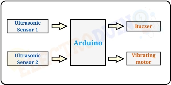
This project is build based on a simple concept. Five key components are needed to build this project, these are two ultrasonic Sensors, an Arduino board, Buzzer, and a Vibration motor. Two ultrasonic sensors are used to detects obstacles at different hight. Then these sensors send data to the Arduino board. Now the Arduino calculates the distance between the sensor and the obstacle. Whenever an obstacle comes near these sensors, then the Arduino sends operating voltage to the Buzzer and Vibration motor. Then the Buzzer and Vibration motor turn on, these are used as indicators.
Block Diagram of Smart Blind Stick Using Arduino
Components Required
| Components Name | Quantity |
| Arduino Nano with a USB cable | 1 |
| Ultrasonic Sensor HC-SR04 | 3 |
| 5v Buzzer | 1 |
| Small Vibrating motor | 1 |
| Toggle switch | 1 |
| 9-volt battery | 1 |
| 9-volt battery connector | 1 |
Required other Parts and Tools
| Tools Name | Quantity |
| PVC pipe diameter 3/4 inch | 2 meter |
| PVC elbow connector diameter 3/4 inch | 1 |
| Plastic board | 1 |
| Soldering Iron | 1 |
| Soldering wire | 1 |
| Soldering flux | 1 |
| Soldering stand | 1 |
| Multimeter | 1 |
| Desoldering pump | 1 |
| Wirecutter | 1 |
| Screwdriver | 1 |
Circuit Diagram/ Schematics of Smart Blind Stick Using Arduino and 2 Ultrasonic Sensors
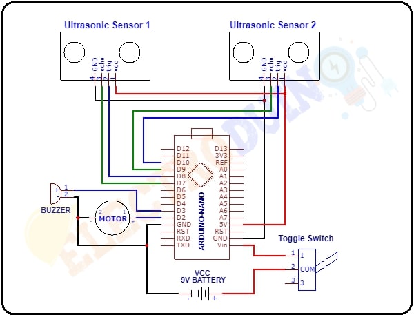
Circuit Wiring
We will show you how all components are connected with Arduino using the following Table.
| Components Pin | Arduino Pin |
| 9-v battery positive(+) terminal | Arduino VIN Pin through the Toggle switch |
| 9-v battery negative(-) terminal | Ground (GND) Pin |
| Ultrasonic Sensor 1 and 2 Vcc Pin | 5v pin |
| Ultrasonic Sensor 1 and 2 Gnd Pin | Ground (GND) Pin |
| Ultrasonic Sensor 1 and 2 Trig Pin | Arduino Digital Pin “D8″ and “D10″ respectively |
| Ultrasonic Sensor 1 and 2 Echo Pin | Arduino Digital Pin “D7″ and “D9″ respectively |
| Buzzer positive terminal | Digital Pin “D3″ |
| Vibrating motor terminal 1 | Digital Pin “D2″ |
| Buzzer Negative terminal and Vibrating motor terminal 2 | Ground (GND) Pin |
Working Principle of Smart Blind Stick Using Arduino
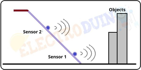
First of all, we should have understood why we are using two Ultrasonic sensors for this project. Here we placed Sensor 1 at the lower part of the walking stick and Sensor 2 at the middle part of the walking stick. Sensor 1 is used to detect objects which are attached to the ground. We have seen some objects which are standing on their legs (like a chair), but there is a gap between the legs of these types of objects. Sensor 2 is used to detect this type of object which are not attached to the ground.
When we turn on the circuit power supply, at the same time the Ultrasonic sensors are transmitting ultrasonic sound waves from the transmitter parts. when any objects come in front of these sensors, then the ultrasonic sound waves reflect back from the object surface to the sensor receiver part, then the sensor receives this wave and generates Output. This output data goes to the Arduino nano. Then the Arduino calculates the distance between the sensor and the objects.
If one of the sensors detects the distance is less than 80 cm. Then the Arduino sends operating voltage to the Buzzer and the Vibrating motor. Now the buzzer generates sound and the motor start Vibrating.
If one of the sensors detects the distance is less than 60 cm. Again the Arduino sends operating voltage to the Buzzer and the Vibrating motor. But this time buzzer generates sound and the motor start Vibrating faster.
When the sensors do not detect an object. In this condition, the buzzer and the motor are stopped.
| Interfacing Ultrasonic Sensor with Arduino | Ultrasonic Sensor Arduino Code |
Arduino Code
/*
 * Program for Smart Blind Walking Stick Using Arduino and two Ultrasonic Sensors.
 * Code by ELECTRODUINO
 * Website: www.electroduino.com
 */

int trigpin1 = 8; // Defines Tirg pins of the Ultrasonic Sensor 1
int echopin1 = 7; // Defines Echo pins of the Ultrasonic Sensor 1

int trigpin2 = 10; // Defines Tirg pins of the Ultrasonic Sensor 2
int echopin2 = 9; // Defines Echo pins of the Ultrasonic Sensor 2

int BUZZpin = 3; // Defines BUZZER pins
int Vmotor = 2; // Defines Vibrating motor pins

void setup()
 {
  Serial.begin (9600);
  pinMode(trigpin1,OUTPUT); // Sets the trigPin1 as an Output
  pinMode(echopin1,INPUT);  // Sets the echoPin1 as an Input

  pinMode(trigpin2,OUTPUT); // Sets the trigPin1 as an Output
  pinMode(echopin2,INPUT);  // Sets the echoPin1 as an Input

  pinMode(BUZZpin,OUTPUT); // Sets the BUZZER as an Output
  pinMode(Vmotor,OUTPUT); // Sets the BUZZER as an Output

  }

  void loop()
  {
    // measure distane using ultrasonic sensor 1 and Print sensor deta in serial monitor
    long duration1, distance1;
    digitalWrite(trigpin1,LOW);
    delayMicroseconds(2);
    digitalWrite(trigpin1,HIGH);
    delayMicroseconds(10);
    digitalWrite(trigpin1,LOW);
    duration1 = pulseIn(echopin1,HIGH);
    distance1 = (duration1/2) / 29.1;
    Serial.print("distance1:");
    Serial.println(distance1); // TO Print sensor deta in serial monitor
   // delay(500); // delay for clearly shown in serial monitor

    // measure distane using ultrasonic sensor 2 and Print sensor deta in serial monitor
    long duration2, distance2;
    digitalWrite(trigpin2,LOW);
    delayMicroseconds(2);
    digitalWrite(trigpin2,HIGH);
    delayMicroseconds(10);
    digitalWrite(trigpin2,LOW);
    duration2 = pulseIn(echopin2,HIGH);
    distance2 = (duration2/2) / 29.1;
    Serial.print("distance2:");
    Serial.println(distance2); // TO Print sensor deta in serial monitor
   // delay(500); // delay for clearly shown in serial monitor


    //if any sensor senses distance less than 80 cm then the buzzer generates sound and the motor starts vibrating.
    if(distance1 <= 80 || distance2 <= 80 )
    {
      digitalWrite(BUZZpin,HIGH);
      delay(100);
      digitalWrite(BUZZpin,LOW);
      delay(100);
      digitalWrite(Vmotor,HIGH);
      delay(100);
      digitalWrite(Vmotor,LOW);
      delay(100);
     }

 //if any sensor senses distance less than 40 cm then the buzzer generates sound and the motor starts vibrating faster
    if(distance1 <= 40 || distance2 <= 40 )
    {
      digitalWrite(BUZZpin,HIGH);
      delay(50);
      digitalWrite(BUZZpin,LOW);
      delay(50);
      digitalWrite(Vmotor,HIGH);
      delay(50);
      digitalWrite(Vmotor,LOW);
      delay(50);
     }
   // else the buzzer generates sound after every 3 seconds for indicating the device is on
    else
     {
      digitalWrite(BUZZpin,LOW);
      digitalWrite(Vmotor,LOW);
      }
   }