
BC547 Transistor – Pin Diagram, Specifications, Datasheet
Hello friends! Welcome back to ElectroDuino. This blog is based on the BC547 Transistor – Pin Diagram, Specifications & Working Principle. Here we will discuss the Introduction to the BC547 transistor, Pin diagram, How it Works, Features, Equivalent transistor, and its applications.
Introduction
The BC547 is an NPN Bipolar Junction Transistor (BJT). It consists of three terminals, these are emitter (E), collector(C), and base (B). If a small amount of current is applied to the base terminal of this transistor, it can control a large amount of currents at the collector and emitter terminal. This transistor is normally used for amplification of current as well as switching purposes. The maximum gain current of the BC547 transistor is 800A.
Transistor Pin Configuration

|
Pin No |
Pin Name |
Symbol |
Work |
|
1 |
Collector |
C |
The flow of current will be through the collector terminal. |
|
2 |
Base |
B |
This pin controls the transistor biasing. |
|
3 |
Emitter |
E |
The current supplies out through the emitter terminal. |
Working States of BC547 Transistor
This transistor has two working states, one is Forward Bias and another one is Reverse Bias.
BC547 is an NPN transistor. So, when we will apply positive voltage at the base terminal of this transistor, then it starts working as Forward Bias. In forward bias mode, this transistor allows the flow of current through the collector & emitter.
When we will do not apply any voltage (or apply negative voltage) at the base terminal of this transistor, then it starts working as Reverse Bias. In reverse bias mode, this transistor doesn’t allow the flow of current through the collector & emitter.
Working of BC547 Transistor
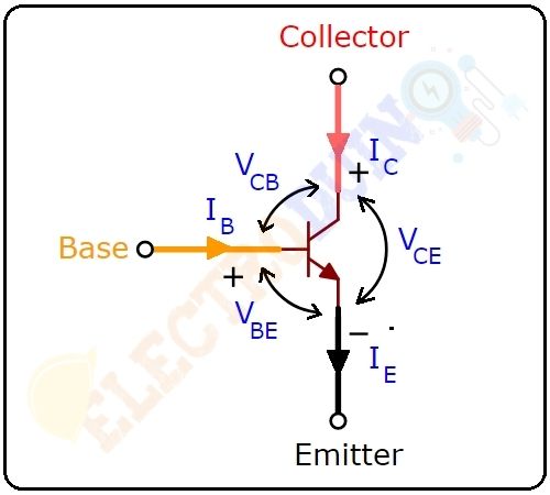
When the input voltage is applied at the base terminal, then some amount of current starts to flow from the base terminal to the emitter terminal and controls the current at the collector terminal. The voltage between the base terminal and the emitter terminal (VBE), is negative at the emitter terminal and positive at the base terminal for its NPN construction. The voltage between the collector and the base (VCB), is negative at the base and positive at the collector terminal and the voltage between the collector and the emitter (VCE), is negative at the emitter and positive at the collector terminal.
BC547 Transistor as A Switch
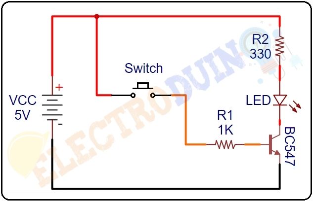
Here we will explain, how the BC547 transistor works as a switch, using the below circuit diagram. The transistor is operated in the Saturation and Cutoff Region when we will use it as a Switch. This transistor biasing current should maximum of 5mA. If we apply more than 5mA will damage the Transistor. Therefore always we need to connect a resistor in series with base pin. This resistor value (RB) can be calculated using the below formulae.
RB = VBE / IB
When the switch is in open condition, so the voltage does not apply to the base terminal. Now the transistor is in Reverse Bias states, so the current does not flow through the collector & emitter. In this condition, the LED is turn off.
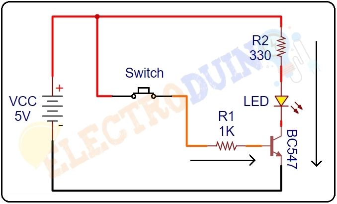
When we will press the switch, then it is in close condition, so the voltage is applied to the base terminal. Now the transistor is in Forward Bias states, so the current starts flowing through the collector & emitter. In this condition, the LED will turn on.
This way current is flowing through the circuit: Power Supply → Resistor → LED → Collector-Emitter → Ground
BC547 Transistor as An Amplifier
The transistor is operated in the Active Region when we will use it as an Amplifier. This transistor can amplify power, voltage, and current at different configurations.
Different configurations are used in amplifier circuits, Some of them are
- Common emitter amplifier
- Common collector amplifier
- Common base amplifier
The most popular and mostly used configuration is the common emitter amplifier. We can be calculated the DC current gain using the below formulae, when using the transistor as an Amplifier.
DC Current Gain = IC/IB
Where, IC is the Collector Current and IB is the Base Current.
BC547 Transistor Features
- Transistor Type: NPN
- The gain of DC current (hFE) = 800 A
- Continuous collector current (Ic) = 100mA
- emitter-base voltage (VBE) = 6V
- base current (IB) = 5mA max
- The transition frequency = 300MHz
- Power dissipation = 625mW
- Package-Type: TO-92
- Max Storage & Operating temperature : -65 to +150 Centigrade
BC547 Equivalent Transistors
BC549, BC548, 2N2222 , 2N3904, 2N3906, 2N3055
Applications of BC547
BC547 is normally used for:
- Current Amplification.
- Fast switching.
- Pulse Width Modulation.
- Audio Amplifiers
- Transistor Darlington Pairs
- Drivers like an LED driver, Relay Driver, etc.


Pingback: PIR Sensor Burglar Alarm System Circuit using 555 Timer IC »