

Capacitor Definition, Symbol, Unit, Working Principle, Application
Hello friends! Welcome back to ElectroDuino. This blog is based on Capacitor. In the dynamic world of electronics, where innovation drives progress, capacitors stand as silent yet indispensable pillars of technology. From powering everyday gadgets to enabling complex industrial systems, capacitors play a vital role in a multitude of applications. Their ability to store and release electrical energy has made them indispensable in modern technology. In this article, we will discuss “What is a Capacitor, Capacitance, Construction, SI Unit, Symbols, Working Principles, Voltage Rating, and Applications”.
What is a Capacitor?
A capacitor is a two-terminal passive electronic component designed to store and release electrical energy in the form of potential differences between its plates.
They are made up of two metallic plates (conductive plates) that are as close to each other as possible without touching and the space between the plates is filled by an insulating material known as a dielectric (a material that does not conduct electricity). Unlike batteries, which produce and store energy through chemical reactions, capacitors store energy in an electric field created between two conductive plates.
What is Dielectric Material?
The non-conducting material (insulating material) is present between the two metallic plates of a capacitor is known as dielectric. This dielectric can be made of various materials, including vacuum, air, mica, paper, ceramic, aluminium etc.
The name of the capacitor is given by the dielectric material used for its construction. For example, ceramic capacitors often use a ceramic dielectric like titanium oxide or barium titanate, while film capacitors utilize a thin polymer film. Each dielectric material is chosen based on the desired properties of the capacitor, such as capacitance (measured in farads) or the ability to withstand voltage
Construction of a Capacitor
The physical construction of capacitors may vary, but the fundamental components remain consistent. Imagine a sandwich, now replace the slices of bread with conducting plates and the fillings with an insulating material called a dielectric. This is a simplified view of how a capacitor is constructed.
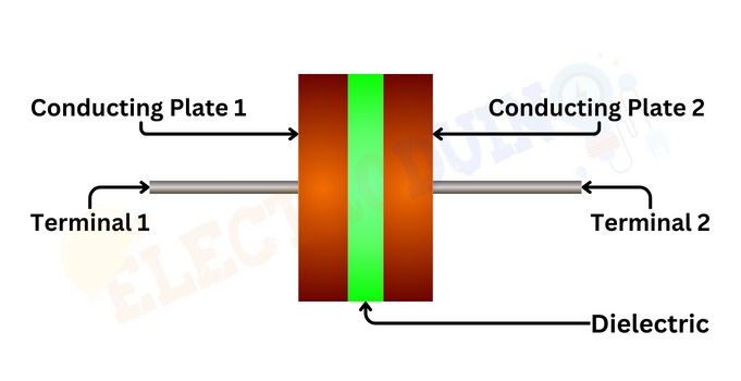
At its most basic, a capacitor consists of two conducting plates made of materials like aluminium or tantalum, positioned parallel to each other with a small space between them. The space between these plates is filled with a dielectric material, which determines the capacitor’s performance characteristics such as capacitance, voltage rating, and temperature stability. Dielectrics can range from simple air gaps to specialized materials like glass, paper, plastic, ceramics, or electrolytes.
The Conducting plates, often foil-like in structure, are intricately designed to maximize surface area and minimize the distance between them. This architecture is crucial; it allows the capacitor to store the maximum amount of electric charge per unit voltage applied. Each plate is connected to an external terminal, allowing for the connection to an electrical circuit.
Each plate is connected to an external terminal, enabling the capacitor to be integrated into an electrical circuit.
Symbol of a Capacitor
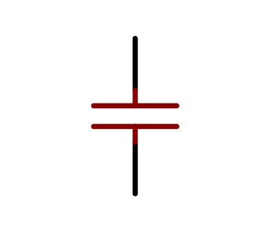
The standard symbol used to represent a capacitor in circuit diagrams consists of two parallel lines representing the plates of the capacitor, separated by a gap to signify the dielectric material.
While the basic symbol of a capacitor provides a general representation of the component, there are variations and additional markings that can be included to convey specific characteristics and properties of the capacitor:
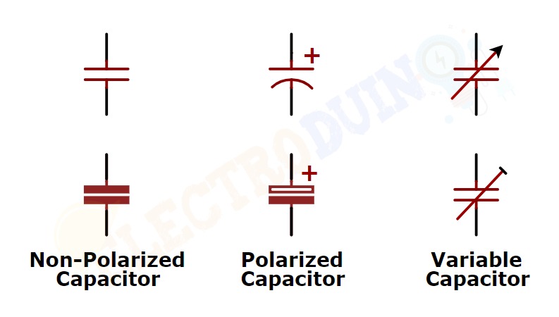
Non-Polarized Capacitors:
Non-polarized capacitors, which can be connected in any direction within a circuit, are represented with a straight line on both sides of the parallel lines, indicating the absence of polarity.
Polarized Capacitors:
Electrolytic capacitors, which are polarized and have a specific orientation for correct operation, are represented with a curved line on one side of the parallel lines to indicate the polarity. The curved line indicates the negative plate.
Variable Capacitors:
Variable capacitors, which have an adjustable capacitance, are depicted with a capacitor symbol where one of the parallel lines is replaced by an arrow or a straight line with a diagonal, indicating the adjustable nature of the capacitance.
Unit of Capacitor
Capacitance is a fundamental property that defines a capacitor’s ability to store electrical charge. The International System of Units or SI unit of capacitance is Farad, represented by the symbol F. The unit is mainly named in honour of the English physicist Michael Faraday.
What is a Farad?
One farad is defined as the capacitance of a capacitor that stores one coulomb of electrical charge when a voltage of one volt is applied across its terminals.
Mathematically, the farad can be expressed as:
1 F=1 C/V
Where:
- F is one farad
- C is one coulomb of charge
- V is one volt of applied voltage
The farad is a relatively large unit of capacitance. Hence, in practical applications, the capacitance is usually measured in the sub-units of Farads, such as milli-farad (mF), micro-farads (µF), nano-farad(nF) or pico-farads (pF). These subunits are derived from the farad as follows:
- 1F =10^3 μF
- 1F =10^6 μF
- 1 F=10^9 nF
- 1 F=10^12 pF
Working Principle of a Capacitor
The working principle of a capacitor revolves around the accumulation and retention of electric charge between two conductive plates separated by a non-conductive material. This simple yet ingenious design enables capacitors to store energy in the form of an electric field, which can be released when required.
Initial State:
At the beginning of the charging process, the capacitor is in its discharged state, which means there is no charge stored on its plates. The negative and positive charges on the two conducting plates of the capacitor are in equilibrium. As resulting there is no tendency for a capacitor to get charged or discharged.

Charging Phase:
When the capacitor is connected to a voltage source, such as a battery or external Power Supply, the charging process initiates. After connecting the voltage source, a potential difference (voltage) is established across the terminals of the capacitor.
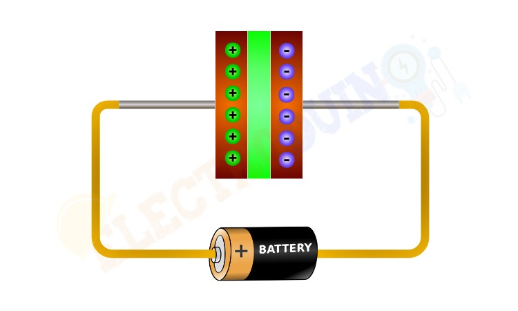
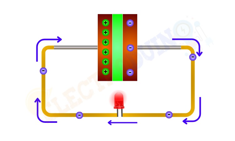
The current will try to flow, or we can say that the electrons from the conducting plate of the capacitor connected to the positive lead of the power supply (battery) will start moving to the conducting plate connected to the negative lead of the power supply (battery). Because of the dielectric material between the conducting plates of the capacitor, the electrons won’t be able to pass through the capacitor. For this reason, Electrons will start accumulating on that plate which is connected to the negative lead of the power supply.

This accumulation of electrons on one plate, creates an excess of negative charge on the plate, effectively making it more negatively charged compared to the other plate. While an equal number of electrons are drawn away from the other plate, leaving it with a positive charge. This accumulation and separation of charges across the capacitor’s plates create an electric field in the dielectric material between them, storing electrical energy in the form of an electric field. This process continues until the potential difference across the plates equals the applied voltage.

Mathematically, the charge (Q) stored by a capacitor is directly proportional to the applied voltage (V) and the capacitance (C) of the capacitor, as described by the equation
Q = CV
Where
- Q is the Charge stored by the capacitor
- C is the capacitance measured in farads.
- V is the applied voltage
Discharging Process:
When we connect a load to the terminals of the fully charged capacitor then the electric field across the dielectric starts to collapse, and the stored electrical energy begins to flow out of the capacitor. The accumulated electrons on the negatively charged plate start moving towards the positively charged plate through the load. The flow of current continues until the charges on the plates reach equilibrium, at which point the capacitor is fully discharged.
Rate of Discharge:
The rate at which a capacitor discharges depends on its capacitance and the resistance of the external circuit through which it is discharging. A higher capacitance value or a lower resistance value will result in a slower discharge rate, while a lower capacitance value or a higher resistance value will lead to a faster discharge rate.
Mathematically, the discharge of a capacitor can be described by the exponential decay formula:
V(t)=V0 × e− t/RC
Where:
- V(t) is the voltage across the capacitor at time
- V0 is the initial voltage across the capacitor
- R is the resistance of the discharging circuit
- C is the capacitance of the capacitor
- t is the time elapsed since the start of the discharging process
Voltage Rating of Capacitors
The voltage rating of a capacitor refers to the maximum voltage that can be applied across its terminals without causing electrical breakdown or permanent damage to the dielectric material and the internal structure of the capacitor. Expressed in volts (V), this specification serves as a critical parameter for selecting capacitors suitable for specific operating conditions and applications. Different dielectric materials, such as ceramic, tantalum, aluminium electrolytic, and polyester film, have different breakdown voltages, which in turn, influence the voltage rating of the capacitor. Some common voltage ratings and their typical applications include:
- Low Voltage (LV) Capacitors (up to 50V): Used in consumer electronics, audio equipment, and low-power circuits.
- Medium Voltage (MV) Capacitors (50V to 500V): Commonly used in power supplies, lighting systems, and motor control circuits.
- High Voltage (HV) Capacitors (500V and above): Employed in high-power applications, power distribution systems, and industrial equipment.
How to Select the Right Voltage-Rated Capacitor:
When selecting a capacitor for a specific application, it is vital to consider the voltage requirements of the circuit to ensure the chosen capacitor can safely handle the applied voltage. Here are some guidelines to help you select the right voltage-rated capacitor:
- Identify Circuit Voltage:Determine the maximum voltage that will be applied across the capacitor in the circuit. This value should be below the capacitor’s rated voltage to provide a safety margin and ensure reliable operation.
- Choose a Capacitor with Adequate Voltage Rating:Select a capacitor with a voltage rating that exceeds the maximum circuit voltage. It is recommended to choose a capacitor with a voltage rating at least 1.5 to 2 times higher than the maximum circuit voltage to account for voltage spikes and fluctuations.
- Consider Application Requirements: Depending on the specific application, such as filtering, decoupling, or energy storage, choose a capacitor with the appropriate capacitance and voltage rating to meet the circuit’s requirements effectively.
Applications of Capacitors
Capacitors find a wide range of applications across different industries and technologies. Some common applications include:
Power Supply Filtering:
One of the primary applications of capacitors is in power supply circuits to filter out unwanted noise and fluctuations, ensuring a stable and reliable DC output voltage. By smoothing the rectified AC voltage and suppressing voltage spikes, capacitors contribute to the efficient and uninterrupted operation of electronic devices, ranging from consumer electronics to industrial equipment.
Signal Coupling and Decoupling:
In the realm of signal processing and communication systems, capacitors serve as indispensable tools for coupling and decoupling signals. They allow the passage of AC signals while blocking DC components, facilitating the transfer of signals between different stages of a circuit without unwanted distortion or interference. This application is particularly crucial in audio amplifiers, radio frequency circuits, and data transmission systems.
Energy Storage and Discharge:
Capacitors serve as temporary energy storage devices in applications requiring quick bursts of power, such as camera flashes, defibrillators, and pulse circuits. Their ability to discharge rapidly makes them ideal for delivering high power in short durations, making them invaluable in medical devices, automotive systems, and photography equipment.
Timing Circuits and Oscillators:
Capacitors, in conjunction with resistors and other components, play a key role in controlling the timing of electronic circuits. In oscillators and timing circuits, capacitors determine the frequency of oscillations and the duration of pulses, essential for functions like clock generation, pulse generation, and timing control in digital systems.
Signal Filtering and Processing:
In audio equipment, telecommunications, and data communication systems, capacitors are employed in filter circuits to attenuate or block specific frequencies, enabling the extraction of desired signals and the suppression of unwanted noise and interference. This filtering capability is crucial for ensuring clear sound quality, reliable data transmission, and efficient signal processing.
Voltage Regulation and Surge Protection:
Capacitors are utilized in voltage regulation circuits to maintain a constant output voltage and protect sensitive electronic components from voltage surges and transients. By absorbing and dissipating excess energy, capacitors safeguard electronic devices from damage and ensure reliable operation in fluctuating voltage conditions.
Motor Starting and Power Factor Correction:
Capacitors play a crucial role in starting single-phase induction motors by creating an initial phase shift in the motor windings, initiating rotation. Additionally, capacitors are employed for power factor correction in electrical systems to improve efficiency and reduce energy losses, particularly in industrial and commercial applications with inductive loads.
Energy Harvesting and Renewable Energy:
In the pursuit of sustainable energy solutions, capacitors play a vital role in energy harvesting and storage systems. Capacitors store energy generated from renewable sources such as solar panels or wind turbines, enabling efficient energy management and utilization in off-grid or remote applications.