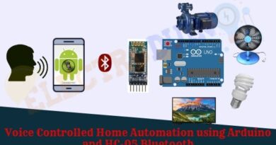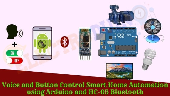
Voice and Button Control Smart Home Automation Project using Bluetooth and Arduino
Hello friends! Welcome back to ElectroDuino. This blog is base on Voice and Button Control Smart Home Automation Project using Bluetooth and Arduino. Here we will discuss Introduction to Voice and Button control Smart Home Automation Project, Project Concept, Block Diagram, Components Required, Circuit Diagram, Working Principle, and Arduino Code.
Introduction
The home automation system is one of the trending products that is reduced human effort. In these modern days, everyone wants their smart home where all electronic or electrical devices and home appliances can be controlled remotely. In the previous blog tutorial, we are design different types of home automation systems, like IR remote control, RF Based, GSM-based, IoT-based, Bluetooth Voice Control, and Bluetooth control home automation in Home Automation Series. In this project, we will make a new type of Bluetooth control Home Automation system, where we can control home appliances wirelessly through Bluetooth communication technology. In this smart home automation system, we will control home appliances using the Voice command and button command.
Project Concept
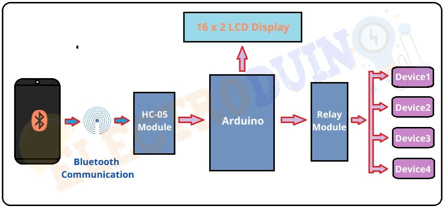
This is the combined project of the Button and voice control home automation. Here we need the same components that are used in the previous Bluetooth home automation projects. But here we will use another App (Application). This App (Application) can read our voice command as well as button command in a single dashboard. The key components of the Voice and switch control smart home automation are the Bluetooth module, Arduino board, relay module, LCD Display, Android Phone, and a Bluetooth App. This App (Application) can read our voice command as well as button command in a single dashboard. This app sends our command (voice or button) to the Bluetooth module. Then the Bluetooth module receives this data and passes it to the Arduino. Then Arduino sends commands to the relay module to control the home appliances. Here we will also use a display module that shows the home appliances status (ON or OFF)
Block Diagram of Voice and Button Control Smart Home Automation Project
Components Required
| Components Name | Quantity |
| Arduino NANO | 1 |
| HC-05 Bluetooth Module | 1 |
| 4 Channel Relay Module | 1 |
| AC Bulb with Holder and Wire | 4 |
| PCB Prototyping board | 1 |
| 12V DC Power supply | 1 |
| 220V AC Power supply | |
| Connecting wires | As required in the circuit diagram |
| Smart Phone (Bluetooth supported) | 1 |
| Bluetooth Controller App | Available in Google Play Store |
Tools Required
| Tools Name | Quantity |
| Soldering Iron | 1 |
| Soldering wire | 1 |
| Soldering flux | 1 |
| Soldering stand | 1 |
| Multimeter | 1 |
| Desoldering pump | 1 |
| Wirecutter | 1 |
| Screwdriver | 1 |
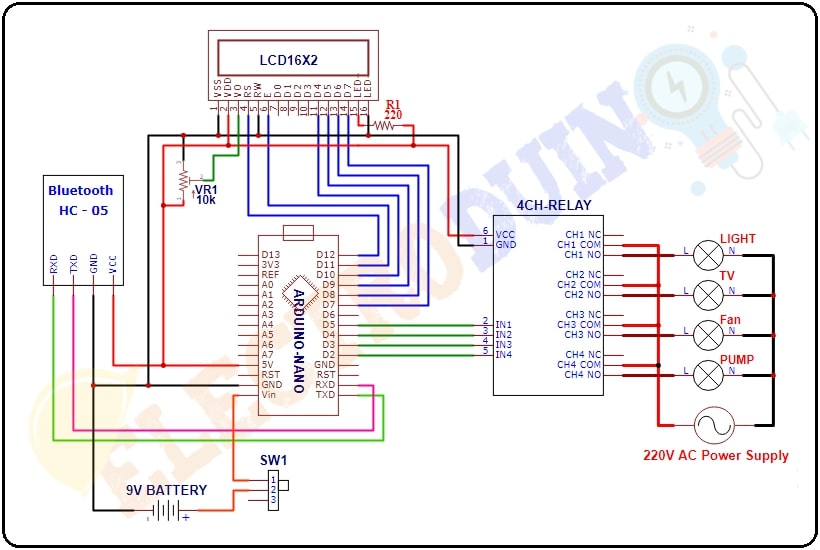
Circuit Diagram of Voice and Button Control Smart Home Automation Project
Bluetooth App configure
First of all, open the Play Store of your Android Smartphone and search for “Control Arduino With Bluetooth-BlueUnio”. Then you will get this App. Now install this app.
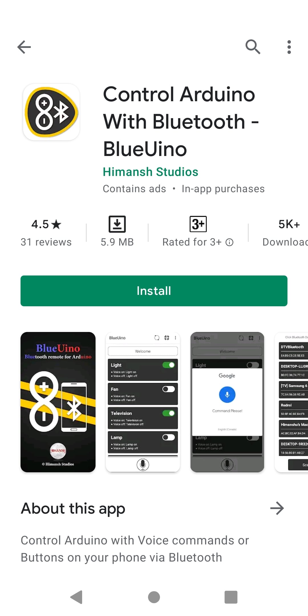
After completing the installation process, open the app. Make sure the circuit is connected to the power supply and the Bluetooth module is on. Also, make sure the Bluetooth module pair with your smartphone. You can pair your phone with the HC-05 Bluetooth Module like we normally pair the phone with Bluetooth earphones or speakers. Then you will come on the App dashboard. Here you can see the Buttons and a mic symbol for the Voice command. Also, you will see two Settings buttons on the top right corner of the app.

Settings button 1
At first, Click on the Settings button 1,if your smartphone pair with the HC-05 Bluetooth module, then you can see the “HC-05 Bluetooth” name on this page. Now click on it and select it. If your app is successfully connected to the Bluetooth module, then you can see the LED on the Bluetooth is start blinking with a delay.

Settings button 2
After complete the App setup/configuration, now we need to Set the load values (Code) of the App buttons. When we click a Button or send a particular voice command, then the App sends a particular load value (Code) to the Arduino. Using this Settings button 2 we can change the button name, Voice commands, and load value (Code). So, click on the Settings button 2, then you will get this interface.

Here we will change the button name, Voice commands, and load value (Code). The list is below
| App Button No. | App Button Name | App Button Status | Voice Commands | Load Values (CODE) | Device status | Control Relay (Relay Pin) |
| 1 | Light | ON | turn on Light | 1 | Light On | Relay-1 (IN1) |
| OFF | turn off Light | A | Light Off | |||
| 2 | Fan | ON | turn on Fan | 2 | Fan On | Relay-2 (IN2) |
| OFF | turn off Fan | B | Fan Off | |||
| 3 | Television | ON | turn on Television | 3 | Television On | Relay-3 (IN3) |
| OFF | turn off Television | C | Television Off | |||
| 4 | Pump | ON | turn on Pump | 4 | Pump On | Relay-4 (IN4) |
| OFF | turn off Pump | D | Pump Off | |||
| 5 | All Device | ON | turn on All | 9 | All Devices (1, 2, 3 & 4) On | Relay-1, Relay-2 Relay-3, Relay-4 (IN1, IN2, IN3, IN4) |
| OFF | turn off All | I | All Devices (1, 2, 3 & 4) Off |
Working Principle of Voice and Button Control Smart Home Automation Project
When we pressed any button or say a voice command in the App, the App sends a unique load value according to the button Settings. The HC-05 Bluetooth Module received this unique load value and send it to the Arduino. Then, the Arduino compares the value with the predefined load value in the Arduino code. If this value is matching, then the Arduino sends operating voltage to the relay module. also, we can see the Device status (on or off) on the 16×2 LCD Display.
For example, when we Press the “Light” button or say “turn on Light” voice command, then the app sends Load value “1” to the Bluetooth module. Then the Arduino gets this value through the Bluetooth module. Then the Arduino sends Low(0) voltage to the Input-1 (IN1) pin of the relay module. Now the relay is in On mode. So, the Light will also turn on, which is connected to the relay-1 of the relay module. At the same time, the “D1 (Device 1) is ON” status print on the 16×2 LCD Display Module.
when we again Press the App “Light” button or say “turn off Light” voice command, then the app sends Load value “A” to the Bluetooth module. Again the Arduino gets this value through the Bluetooth module. But this time the Arduino sends a High(5v) input voltage to the Input-1 (IN1) pin of the relay module. Now the relay is in Off mode. So the Light will also turn off, which is connected to the relay-1 of the relay module. At the same time, the “D1 (Device 1) is Off” status print on the 16×2 LCD Display Module.
In this way, we can control all relays of the 4 channel Relay module through the App using Button and Voice Command.
Arduino Code
/*
Voice and Button Control Smart Home Automation
http://www.electroduino.com
*/
//libraries for LCD Display
#include <LiquidCrystal.h>
// Define LCD display pins
LiquidCrystal lcd(12,11,10,9,8,7);

const int Device1 = 6; // Relay pin 1 (IN1)
const int Device2 = 5; // Relay pin 2 (IN2)
const int Device3 = 4; // Relay pin 3 (IN3)
const int Device4 = 3; // Relay pin 4 (IN4)

 char Val;
void setup()
 {
  Serial.begin(9600); //Sets the baud for serial data transmission
  // Set Relay pins as OUTPUT
  pinMode(Device1, OUTPUT);
  pinMode(Device2, OUTPUT);
  pinMode(Device3, OUTPUT);
  pinMode(Device4, OUTPUT);
  // Print massage on LCD Display
  lcd.clear();
  lcd.begin(16, 2);
  lcd.setCursor(0,0);
  lcd.print("Voice & Button");
  lcd.setCursor(0,1);
  lcd.print("Home Automation");
  delay(2000);
  // All devics are Off when system is on
  digitalWrite(Device1, HIGH);
  digitalWrite(Device2, HIGH);
  digitalWrite(Device3, HIGH);
  digitalWrite(Device4, HIGH);

  // Print massage All devics are Off when system is on
  lcd.clear();
  lcd.setCursor(0,0);
  lcd.print(" D1  D2  D3  D4 ");
  lcd.setCursor(0,1);
  lcd.print("OFF OFF  OFF OFF");
 }

void loop()
 {
  lcd.setCursor(0,0);
  lcd.print(" D1  D2  D3  D4 ");
  // Read data from Bluetooth Module
  if (Serial.available() > 0)
  {
    Val = Serial.read();
    // Print Bluetooth Module data on serial monitor
    Serial.print("VAL: ");
    Serial.println(Val);
    //  When Bluetooth Module data "1" then Relay1 ON
   if (Val == '1')
     {
      digitalWrite(Device1,LOW);
      lcd.setCursor(0,1);
      lcd.print("ON ");
      delay(200);
     }
    //  When Bluetooth Module data "A" then Relay1 OFF
   else if (Val=='A')
     {
      digitalWrite(Device1,HIGH);
      lcd.setCursor(0,1);
      lcd.print("OFF");
      delay(200);
     }
    //  When Bluetooth Module data "2" then Relay2 ON
   else if (Val=='2')
     {
     digitalWrite(Device2,LOW);
     lcd.setCursor(4,1);
     lcd.print("ON ");
     delay(200);
     }
    //  When Bluetooth Module data "B" then Relay2 OFF
   else if (Val=='B')
     {
     digitalWrite(Device2,HIGH);
     lcd.setCursor(4,1);
     lcd.print("OFF");
     delay(200);
     }
    //  When Bluetooth Module data "3" then Relay3 ON
    else if (Val=='3')
      {
      digitalWrite(Device3,LOW);
      lcd.setCursor(9,1);
      lcd.print("ON");
      delay(200);
      }
    //  When Bluetooth Module data "C" then Relay3 OFF
    else if (Val=='C')
     {
     digitalWrite(Device3,HIGH);
     lcd.setCursor(9,1);
     lcd.print("OFF");
     delay(200);
     }
   //  When Bluetooth Module data "4" then Relay4 ON
   else if (Val=='4')
     {
     digitalWrite(Device4,LOW);
     lcd.setCursor(13,1);
     lcd.print("ON    ");
     delay(200);
     }
   //  When Bluetooth Module data "D" then Relay4 OFF
   else if (Val=='D')
     {
     digitalWrite(Device4,HIGH);
     lcd.setCursor(13,1);
     lcd.print("OFF");
     delay(200);
     }
   //  When Bluetooth Module data "9" then All Relay ON
   else if (Val=='9')
     {
      digitalWrite(Device1, LOW);
      digitalWrite(Device2, LOW);
      digitalWrite(Device3, LOW);
      digitalWrite(Device4, LOW);
      lcd.setCursor(0,1);
      lcd.print("ON  ON   ON  ON ");
      delay(200);
     }
   //  When Bluetooth Module data "9" then All Relay OFF
   else if (Val=='I')
     {
      digitalWrite(Device1, HIGH);
      digitalWrite(Device2, HIGH);
      digitalWrite(Device3, HIGH);
      digitalWrite(Device4, HIGH);
      lcd.setCursor(0,1);
      lcd.print("OFF OFF  OFF OFF");
      delay(200);
     }
  }
}