Rain Alarm Circuit using NE555 Timer IC
Hello friends! Welcome back to ElectroDuino. This blog is based on a Simple Rain Alarm Circuit using NE555 Timer IC. Here we will discuss Introduction to Rain Alarm Circuit, Project Concept, Block Diagram, Components Required, Circuit Diagram, and Working Principle.
Introduction
In the rainy season, when we dry our clothes in the sun, we keep an eye on whether it is raining or not. This is a very boring job and breaks our concentration to do other important work. Otherwise, there are some industries and companies where you have to constantly check whether it is raining outside. That’s why these industries and companies have to deploy a worker to check the outside weather. To resolve these problems, in this project tutorial we will be going to design a Simple Rain alarm circuit, which detects the rainwater and warn us by making a loud Sound. This system makes our life so simple, and also saves our time and money.
Project Concept/Overview
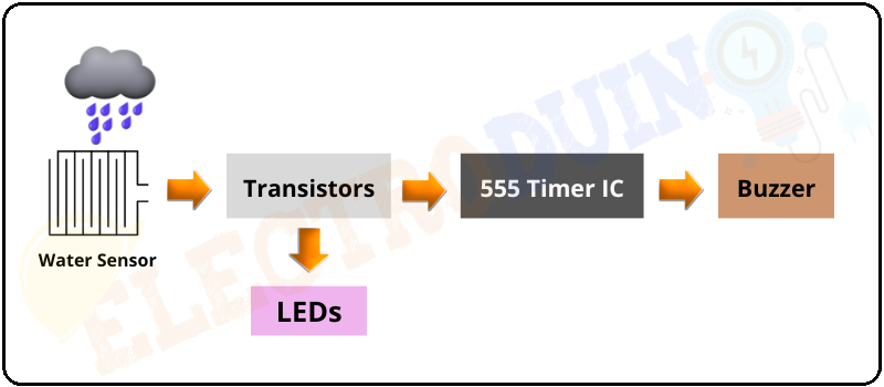
This is a very simple project based on the famous 555 timer IC. The key component of this project circuit the Water Sensor Board, Transistors, 555 Timer IC, Buzzer and LED. Where the water sensor board is used to detect the rainwater that falls on its surface. When rainwater falls on the water sensor, then the rain sensor gives the signal to the base terminal of the transistor. Now the transistor is turned ON and it gives a signal to the 555 timer IC to activate the Buzzer and LED. where the 555 Timer IC is configured in its Astable Mode. The Buzzer and LED are used as an indicator that indicates Rain is falling.
Block Diagram of Simple Rain Alarm Circuit using NE555 Timer IC
Components Required
| Components Name | Quantity |
| NE555 Timer IC (U1) | 1 |
| BC547 Transistor (Q1) | 1 |
| 2N2222 Transistor (Q2, Q3) | 2 |
| Water Sensor Board | 1 |
| 220KΩ Resistors(R1) | 1 |
| 330Ω Resistors (R2) | 4 |
| 10KΩ Resistors (R3) | 1 |
| 470KΩ Resistors (R4) | 1 |
| 3.3KΩ Resistors (R5, R6) | 1 |
| 68K ohm Resistors (R7) | 1 |
| 22μF/50V Electrolytic capacitor (C1) | 1 |
| 100μF Electrolytic Capacitor (C2, C4) | 2 |
| 10ηF Electrolytic capacitor (C3) | 1 |
| 100ρF Ceramic Capacitor (C5) | 1 |
| Red LED | 1 |
| 12v Buzzer | 1 |
| Slide Switch (SW1) | 1 |
| Terminal Block | 1 |
| 12V Power Supply | 1 |
| PCB board | 1 |
| Connecting Wire | As required in the circuit diagram |
Tools Required
| Tools Name | Quantity |
| Soldering Iron | 1 |
| Soldering wire | 1 |
| Soldering flux | 1 |
| Soldering stand | 1 |
| Multimeter | 1 |
| Desoldering pump | 1 |
| Wirecutter | 1 |
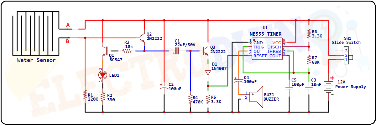
Circuit Diagram Simple Rain Alarm Project using NE555 Timer IC
Working Principle: How the Rain Alarm Circuit Works
When a small amount of rainwater falls on the water sensor board, then the Aluminium Wires on the Water Sensor Board will start conducting and create a close path between points A and B. So the positive supply voltage would get applied on the base of Transistor Q2.
As a result, The Transistor Q2 is turned ON and the current started flowing from the collector terminal to the emitter terminal. The emitter terminal of the transistor Q2 is connected to the base terminal of the transistor Q2 through the Resistor(R3), so the transistor Q1 also turns ON and the Red LED (LED1) starts Glowing.
The emitter terminal of the Transistor Q3 is connected to the Reset Pin (Pin 4) of the 555 Timer IC. And the timer IC is configured in Astable Mode. So, when the transistor Q2 reaches the saturation mode then Capacitor C1 will get shorted and turn on the transistor Q3. At this time the Capacitor C1 will get charged by the Resistor R4. When the transistor Q3 is saturated, the Reset Pin of the 555 Timer IC gets positive voltage.
Now the timer IC becomes active and It will generate oscillation frequency (Pulse signal) at the output pin (Pin 3). This output will turn ON the buzzer and it starts beeping.
Because of the resistor R4 and capacitor C1, the Transistor Q3 will get into the cut-off region after some time. As a result, there will be no positive voltage at the reset pin of the timer IC, So the buzzer will turn OFF and stop making sounds. The sound of the buzzer depends on capacitor C1 and resistor R4.
Output frequency= 1.44/ (R3 +2 x R4)*C1) = 0.72HZ
We should note that initially there was no positive voltage at the Reset PIN of the timer IC because this pin was connected to the ground through resistance R5 (3.3k). So, the 555 timer IC only works when the Reset pin gets positive voltage.
Note:
- Remember that the Rain sensor board should be kept in the open place at 30 to 40 degrees from the ground so that the rainwater does not stay in the sensor for long.
- After detecting the rain, this circuit will automatically switch off the alarm after some time and the LED will glow continuously until the rain stops.