
SIM800l GSM Module
Hello friends! Welcome back to ElectroDuino. This blog is based on SIM800l GSM Module. Here we will discuss the Introduction to SIM800l GSM Module, Pinout/Pin Diagram, Hardware Overview, Features, Power Supply, and applications.
Introduction
SIM800L GSM/GPRS module is a miniature cellular GSM modem from Simcom, which can easily interface with any microcontroller to give the microcontroller GSM functionality, and allows for GPRS transmission. This module connects the microcontroller to the mobile network to make or receive phone calls, send or receive SMS (text messages), and connect to the internet using GPRS, TCP, or IP. Another advantage is It supports quad-band GSM/GPRS network, which means it can work anywhere in the world. These important functionalities as well as the low cost and small footprint make this module more perfect for any project where long-range connectivity is required and also it can be integrated into a great number of IoT projects.
SIM800L GSM/GPRS Module Hardware Overview
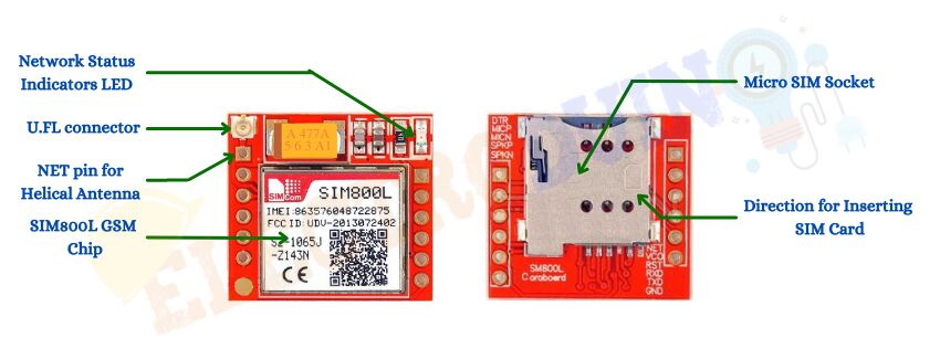
The SIM800L GSM/GPRS module consists of four key components, which take important roles in the work of the module. These key components are SIM800L GSM cellular chip, LED Status Indicators, Antennas, and Micro-SIM socket.
SIM800L GSM cellular chip
On the top surface of the GSM module, we can see a chip is mounted on the module board. This is a Quad-band SIM800L GSM/GPRS cellular chip from SimCom in SMT type. SIM800L supports Quad-band frequency its works on frequencies 850MHz, 900MHz, 1800MHz, and 1900MHz, it can transmit and receive voice, SMS, and data information with low power consumption. The operating voltage of this chip is from 3.4V to 4.4V which makes it ideal to operate by a LiPo battery supply. This chip supports a baud rate from 1200bps to 115200bps with Auto-Baud detection. It has a tiny size of 17.6*15.7*2.3mm which makes it a good choice for embedding into projects without a lot of space.
LED Status Indicators
On the topmost right corner side of the SIM800L Module, we can see an LED that indicates the status of your cellular network. After applying the power supply to the module the LED will blink at three different ratios, which shows three different statuses of your cellular network.
Blink every 1s:
When the LED Blinking with a delay of 1s, then it indicates that the GSM module is running but it hasn’t made the connection to the cellular network yet.
Blink every 2s:
When the LED Blinking with a delay of 2s, then it indicates that The GPRS data connection you requested is active.
Blink every 3s:
When the LED Blinking with a delay of 2s, then it indicates that the module has made contact with the cellular network and it is ready to transmit/receive voice and SMS.
Antennas
An antenna is a vital part of the module, it is used for voice or data communications as well as some SIM commands. SIM800l GSM/GPRS module provides two ways to connect Antennas. There are two types of antennas that can connect to the module one is a Helical GSM antenna and another one is PCB Antenna.
Helical GSM Antenna
The Helical GSM antenna is made of wire, which usually comes with the module. It can be soldered directly to the NET pin on PCB. This type of antenna is very useful in narrow space projects.
PCB Antenna
We can see a U.FL male connector present at the top-left corner of the module, which is used to connect the PCB antenna. This antenna has better performance and allows you to put your module inside a metal case – as long the antenna is outside.
Micro-SIM socket
On the backside of the module, a SIM socket is available, where we can insert an activated 2G micro-SIM card that would work perfectly. When we insert a SIM card into the socket we must ensure that the notch point will upwards. Normally the symbol of the SIM card is engraved on the surface of the SIM socket that helps us to identify the correct direction of SIM inserting.
Pinout/Pin Diagram of SIM800L GSM/GPRS Module
The SIM800L GSM module has 12 pins that are used to connect the module to any microcontroller. The Pinout configuration is explained below:
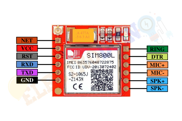
NET: The NET pin is used to attach an external antenna. Where we can solder Helical Antenna which comes along with the module.
VCC: The VCC pin is used to supply the positive (+) voltage to the module. Power supply 3.4V to 4.4V with min 2 Amp required to work the module finely. Remember, never connect it to a 5V power supply, which can destroy your module. Also, It doesn’t work on a 3.3 V power supply.
RST: This pin is a hard reset pin. Pulling this pin low for 100 ms to perform hard reset of the module.
RXD(Receiver): RX pin is used for Serial communication
TXD(Transmitter): TX pin is used for Serial communication
GND: This is the Ground Pin of the module that needs to be connected to the GND pin on the microcontroller.
SPK±: SPK + and SPK – is a differential speaker interface. The two pins of a speaker can be connected to these two pins. The positive pin of the speaker is connected to the SPK+ pin and the negative Pin to the SPK-.
MIC±: MIC+ and MIC- pins are differential microphone inputs. The two pins of the microphone can be connected to these pins. The positive pin of the microphone is connected to the MIC+ pin and the negative Pin to the MIC-.
DTR: Pulling this pin HIGH to activate sleep mode. In sleep mode, the module disables serial communication. Pulling it LOW to deactivate sleep mode, means the module wakes up.
RING: The RING pin acts as a Ring Indicator, which is used in detecting calls and SMS. Basically, this is the ‘interrupt’ out pin from the module. It is by-default high, but when a call is received it gives a LOW pulse for 120ms. Also, it can be configured to pulse when an SMS is received.
Specifications
| IC Chip | SIM800L GSM cellular chip |
| Operating Voltage range | 3.4V ~ 4.4V |
| Recommended supply voltage | 4V |
| Peak Current | 2 A |
| Power consumption |
|
| Supported frequencies | 2G Quad Band (850 / 950 / 1800 /1900 MHz) |
| Transmit Power |
|
| Interface | UART (max. 2.8V) and AT commands |
| SIM card socket | Micro SIM card socket |
| Network Status Indicator | LED |
| Antenna connector | U.FL connector and Header Pin |
| Working temperature range | -40 to + 85 ° C |
| Module size | 25 x 23 mm |
Features
- Receive and make calls using the external speaker and electret microphone
- Receive and send SMS/ Text messages
- Send and receive GPRS data (TCP/IP, HTTP, etc.)
- Scan and receive FM radio broadcasts
- GPRS multi-slot class12 connectivity: max. 85.6kbps(download/upload)
- GPRS mobile station class B
- Controlled by AT Command (3GPP TS 27.007, 27.005 and SIMCOM enhanced AT Commands)
- Supports Real-Time Clock
- Supports A-GPS
- Low power consumption, 1mA in sleep mode
Power Supply for SIM800L GSM Module
One of the biggest issues with the SIM800L GSM module is the power supply to the module. If the power supply can’t fulfill the required current well, then the module can’t make the connection to the cellular network or it will shut down/reset in the middle of the action.
The operating voltage range of the module is 3.4- to 4.4-V. But another problem is the SIM800L module doesn’t have an integrated voltage regulator. So, we need an external power supply between 3.4V to 4.4V (Ideal 4.1V). Also, remember that this module is a bit power-hungry and the current consumption can be up to 2 A in peaks. So, the power supply should be able to source 2A.
Application
- Home automation
- Emergency systems
- Remote sensing
- Communication


