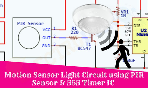
Motion Sensor Light Circuit using PIR Sensor and 555 Timer IC
Hello friends! Welcome back to ElectroDuino. This blog is based on how to make Motion Sensor Light Circuit using PIR Sensor and 555 Timer IC. Here we will discuss the Introduction to the Motion Sensor Light Circuit, Project Concept, Block Diagram, Components Required, Circuit Diagram, and Working Principle.
Introduction
At night time when we enter a dark room or at midnight when waking up to go washroom that time we face problem to find out the switchboard to turn the light. To solve this problem in this project tutorial we will be going to learn how to make a Motion Sensor Light Circuit using PIR Sensor and 555 Timer IC. The Motion Sensor Light Circuit is a very simple and compact device, which consists of a PIR motion Sensor and 555 Timer IC. When it detects any human body or animal then it turns on the light for a few seconds and turns off the light automatically. As well as we can be used it as a thief identification device, hence we need to place it on the outside, when any thief will come in front of this device, then the light will turn on and we can easily detect the thief. Also, we can use this device in different ways, like an Automatic home light, automatic garden light, Bathroom light, Automatic Tablet Lamp, etc.
Project Concept Motion Sensor Light Circuit using PIR Sensor and 555 Timer IC
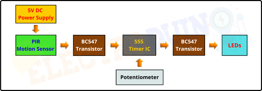
The Motion Sensor Light Circuit project Concept is very simple and easy to build. The key components of this project are the PIR motion sensor, 555 Timer IC, BC547 Transistors, and LEDs. The famous 555 Timer IC is the building base of this project, it controls all the operations. The PIR motion sensor is used to detect the motion of any human body, animal, or any moving thing. When the PIR Sensor detects any human body movement, it generates HIGH (+5V) output voltage. Then this High output voltage will activate the BC547 Transistor-1 and it acts as a close switch. As a result, the transistor will connect the trigger pin of the NE555 timer IC to the ground, then the timer IC produces high output and it will activate the BC547 Transistor-2. Now, this transistor acts as a close switch, which will turn on the LEDs.
Block Diagram of Motion Sensor Light Circuit using PIR Sensor and 555 Timer IC
Components Required
| Components Name | Quantity |
| NE555 Timer IC | 1 |
| CD4017 Counter IC | 1 |
| 10K ohm Resistor (R1) | 1 |
| 1K ohm Resistor (R2) | 1 |
| 150 ohm Resistor (R3 – R12) |
10 |
| 10uf/16v Electrolytic Capacitor (C1) | 1 |
| 0.01uf Ceramic Capacitor (C2) | 1 |
| 10K ohm Potentiometer (VR1) | 1 |
| LED | 11 |
| 9v Power Supply | 1 |
| Slide Switch | 1 |
| PCB board | 1 |
| Connecting wires | As required in the circuit diagram |
Tools Required
| Tools Name | Quantity |
| Soldering Iron | 1 |
| Soldering wire | 1 |
| Soldering flux | 1 |
| Soldering stand | 1 |
| Multimeter | 1 |
| Desoldering pump | 1 |
| Wirecutter | 1 |
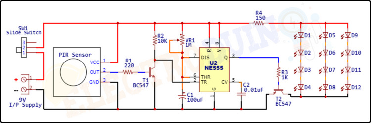
Circuit Diagram of Motion Sensor Light Circuit using PIR Sensor and 555 Timer IC
Working Principle Motion Sensor Light Circuit using PIR Sensor and 555 Timer IC
In this section, we will discuss how the motion sensor light works.
The PIR Sensor Module can detect movement through the detection of infrared radiation levels. Being that any human body or animal are naturally emits radiation, because of their generated body heat. So, When a human body or animal will walking or moving in the detection range of the sensor, the sensor produces High (+5) Output voltage from its data pin.
Then this High output voltage will be going to the Base terminal of the BC547 Transistor -1 (T1) as input. Here this transistor acts as a switching device. So, the High (+5V) voltage at the base terminal activates the Transistor and it acts as a Closed Switch, which creates a closed path between Pin-2 (Trigger Pin) of the 555 timer IC and the Ground. As a result, the Pin-2 (Trigger Pin) of 555 timer IC gets negative (< 1/3Vcc) voltage.
Now inside the 555 timer IC, the Lower comparator becomes HIGH and Flip flop gets Set and the Pin 3 of the Timer ic gives HIGH Output. At the same time, the Timing capacitor C1 starts charging through the Resistor R1. The Output HIGH remains for some time (T). The High Output Time (T) can be calculated using the following formula.
T= 1.1*R1*C1 Seconds
where R1 is in OHM and C1 is in Farads.
In this circuit, we can set the Time (T) duration by adjusting the Potentiometer knob.
The High Output voltage of the 555 timer IC is given to the base terminal of the BC547 transistor-2 (T2). As a result, the transistor is activated and creates a close path between the negative terminal of the LEDs and the ground, which turns on the LEDs. The LEDs turn on until the output of the timer IC becomes low.