
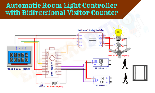
Automatic Room Light Controller with Bidirectional Visitor Counter
Hello friends! Welcome back to ElectroDuino. This blog is based on the Automatic Room Light Controller with Bidirectional Visitor Counter System. Here we will discuss Introduction to Automatic Room Light Controller with Bidirectional Visitor Counter, Project Concept, Block Diagram, Components Required, Circuit Diagram, Working Principle, and Arduino Code.
Introduction
All over the world, the consumption of electricity is increasing day by day. But the main problem is the wastage of electricity is also increasing. Every day we waste electricity in different ways somewhere. One of them is sometimes we have left out our room, office, or classroom and forget to turn off the light, fan, and other electric appliances.
To overcome this problem here we will be going to learn how to make an Automatic Room Light Controller with a Bidirectional Visitor Counter system using Arduino. This system continuously monitors how many visitors entering in the room and how many exiting from the room. And when it detects no visitors inside the room, it turns off the light and fan of that room. In this way, this system can save lots of electricity.
Project Concept/Overview
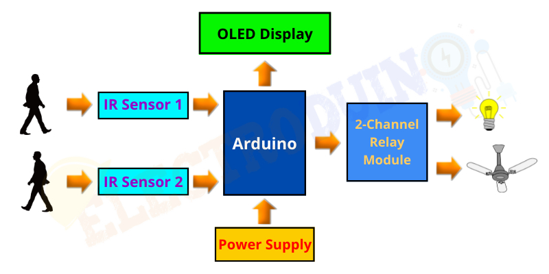
This project is based on Arduino, few major components are needed to build this project. These components are Arduino, two IR sensors, an OLED display, and 2 channel relay module. The Arduino board is used as the main microcontroller that controls this system. Two IR sensors are used to detect the visitor from both directions, i.e., one sensor detects the number of entering visitors and the other one the number of exiting visitors. The OLED display is used to show the total number of entering visitors and the total number of exiting visitors. Also shows the total number of visitors currently present inside the room. The 2-channel relay module is used to control two electric home appliances like light and fan.
Block Diagram of Automatic Room Light Controller with Bidirectional Visitor Counter System using Arduino
Components Required
| Components Name | Quantity |
| Arduino NANO | 1 |
| IR Sensor Module | 2 |
| 16×2 LCD Display Module | 1 |
| 220 ohm Resistor (R1, R2) | 2 |
| 10K ohm Potentiometer (VR1) | 1 |
| 2-Channel Relay Module | 1 |
| 5v Buzzer | 1 |
| 9v Power Supply | 1 |
| Rocker Switch | 1 |
| PCB board | 1 |
| Connecting wires | As required in the circuit diagram |
Tools Required
| Tools Name | Quantity |
| Soldering Iron | 1 |
| Soldering wire | 1 |
| Soldering flux | 1 |
| Soldering stand | 1 |
| Multimeter | 1 |
| Desoldering pump | 1 |
| Wirecutter | 1 |
Software Required

|
Arduino IDE (Integrated Development Environment) |
Required Library
We need to add 2 libraries in Arduino IDE software. These are:
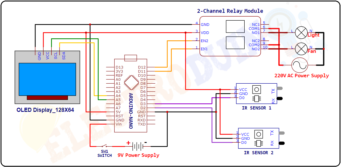
Circuit Diagram of Automatic Room Light Controller with Bidirectional Visitor Counter System using Arduino
Working Principle of Automatic Room Light Controller with Bidirectional Visitor Counter
When a visitor enters the room the sensor-1 detects the visitor (obstacle) and produces a Low (0) output value from its Output Pin. Then the Arduino read this output value from the sensor-1 and counts 1+ using the code. Similarly, When this sensor-1 detects another visitor, the Arduino increment the counting by +1. In this way every time the Arduino adds +1 in the count when the sensor-1 detects visitors and calculates the total number of visitors entering the room.
In the same way, when a visitor leaves the room, the IR sensor-2 detects the visitor (obstacle) and produces a Low (0) output value from the Output Pin. Then the Arduino read this value and counts 1+ using the code. Similarly, every time the Arduino adds +1 in the count when a visitor leaves the room and calculates the total number of exiting visitors.
Every time the Arduino Subtracts the total number of entering visitors from the total number of exiting visitors and calculates the total number of visitors currently present inside the room.
When the Arduino detects the presence of 1 or more than 1 visitors inside the room. Then it grounded (LOW/0V) the input pins (IN1 and IN2) of the 2-Channel Relay Module to active the Relays and turns ON the Light and Fan automatically.
When the Arduino detects No visitor present inside the room. Then it sends a High (5V) voltage to the input pins (IN1 and IN2) of the 2-Channel Relay Module to deactivate the Relays and turns OFF the Light and Fan automatically.
The OLED display shows the total number of entering visitors, the total number of exiting visitors, and the total number of visitors currently present inside the place. And also shows the Light and Fan status (ON/OFF).
Arduino Code for Automatic Room Light Controller with Bidirectional Visitor Counter
 /* Automatic Room Light Controller
    with Bidirectional Visitor Counter
    www.Electroduino.com  */

//OLED Display libraries
#include <Wire.h>
#include <Adafruit_GFX.h>
#include <Adafruit_SSD1306.h>

#define SCREEN_WIDTH 128    // OLED display width, in pixels
#define SCREEN_HEIGHT 64    // OLED display height, in pixels
#define OLED_RESET -1       // Reset pin # (or -1 if sharing Arduino reset pin)
Adafruit_SSD1306 display(SCREEN_WIDTH, SCREEN_HEIGHT, &Wire, OLED_RESET);

#define inSensor 6  // Define IR Sensor 1 connected to D6
#define outSensor 5 // Define IR Sensor 2 connected to D5

#define Light 4 // Define Relay 1 connected to D4
#define Fan 3   // Define Relay 2 connected to D3

// Variables
int inStatus;
int outStatus;
int in;
int out;
int now;
int countin = 0;
int countout = 0;


void setup()
{
  display.begin(SSD1306_SWITCHCAPVCC, 0x3C); //initialize with the I2C addr 0x3C (128x64)
  delay(2000);
  pinMode(inSensor, INPUT);  // initialize digital pin 6 as an input.
  pinMode(outSensor, INPUT); // initialize digital pin 5 as an input.
  pinMode(Light, OUTPUT);    // initialize digital pin 4 as an output.
  pinMode(Fan, OUTPUT);      // initialize digital pin 3 as an output.

  digitalWrite(Light, HIGH); // Relay1 is Off
  digitalWrite(Fan, HIGH);   // Relay2 is Off

  // Print text on display
  display.clearDisplay();
  display.setTextSize(2);
  display.setTextColor(WHITE);
  display.setCursor(20, 00);
  display.print("Welcome");
  display.setTextSize(1);
  display.setTextColor(WHITE);
  display.setCursor(15, 20);
  display.print("ElectroDuino.Com");
  display.setCursor(00, 30);
  display.print("Automatic Room Light Controller with");
  display.setCursor(00, 47);
  display.print("Bidirectional Visitor Counter");
  display.display();
  delay(5000);
}

void loop()
{
  // Read Sensor value
  inStatus =  digitalRead(inSensor);
  outStatus = digitalRead(outSensor);

  //Count the number of visitors entering
  if (inStatus == 0)
   {
    in = countin++;
   }
  // Count the number of visitors exiting
  if (outStatus == 0)
   {
    out = countout++;
   }

   now = in - out;
  // When no visitor is present inside the room
  if (now <= 0)
   {
    digitalWrite(Light, HIGH); // Relay1 is Off
    digitalWrite(Fan, HIGH);   // Relay2 is Off

    display.clearDisplay();
    display.setTextColor(WHITE);

    display.setTextSize(1);
    display.setCursor(15, 0);
    display.print("Current Visitor");

    display.setTextSize(2);
    display.setCursor(05, 20);
    display.print("No Visitor");

    display.setTextSize(1);
    display.setCursor(0, 40);
    display.print("IN: ");
    display.print(in);

    display.setTextSize(1);
    display.setCursor(70, 40);
    display.print("OUT: ");
    display.print(out);

    display.setTextSize(1);
    display.setCursor(10, 55);
    display.print("Light & Fan : OFF ");
    display.display();
    delay(1000);
   }
  // When visitor is present inside the room
  else
   {
    digitalWrite(Light, LOW); // Relay1 is On
    digitalWrite(Fan, LOW); // Relay2 is On
    display.clearDisplay();
    display.setTextColor(WHITE);

    display.setTextSize(1);
    display.setCursor(15, 0);
    display.print("Current Visitor");
    display.setTextSize(2);
    display.setCursor(50, 20);
    display.print(now);

    display.setTextSize(1);
    display.setCursor(0, 40);
    display.print("IN: ");
    display.print(in);

    display.setTextSize(1);
    display.setCursor(70, 40);
    display.print("OUT: ");
    display.print(out);

    display.setTextSize(1);
    display.setCursor(10, 55);
    display.print("Light & Fan : ON ");
    display.display();
    delay(1000);
   }
}


