HC-SR501 (Passive Infrared) PIR Sensor | How it’s Works
Hello friends! Welcome back to ElectroDuino. This blog is base on HC-SR501 (Passive Infrared) PIR Sensor | How (Passive Infrared) PIR Sensor Module Works. Here we will discuss the introduction of the HC-SR501 PIR Sensor module, sensor pin diagram/pinout, sensor hardware overview, How PIR Sensor Module Works, its Specifications, and applications.
Introduction
The PIR sensor is a specially designed electronic sensor that can able to measure or detect Infrared (IR) radiation. PIR Sensor full form is Passive infrared sensor, The “passive” word indicates this sensor does not produce any energy radiation or IR radiation for the detection of objects. This sensor mainly used for motion detection. It is can detect any objects which emit infrared radiation. But the most important thing it does not give information about the moving object. It means when a human passed in front of the sensor then it detects something is moved but it is can not tell us that it is human or other objects.
Note: Who can emit infrared radiation? All objects whose temperature more than zero (0°C) degree centigrade, which emits HEAT energy in the form of IR radiation. We can not see this radiation because it radiates at infrared wavelength. Also, humans and animals are emitting this radiation.
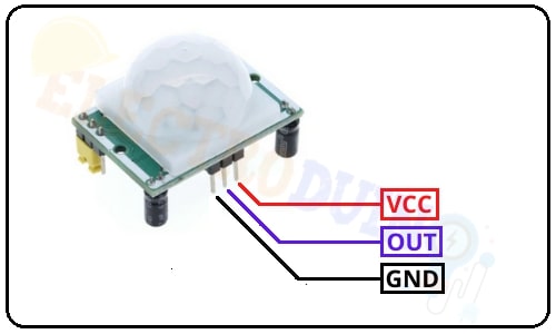
PIR Sensor Pin Diagram
| Pin Number | Pin Name | Description |
| 1 | VCC | We have to connect this pin to the power supply Vcc. Input voltage range from 4.5V to 12V. |
| 2 | OUT | This is the output pin of the PIR sensor. This pin gives Digital pulse high output (3.5V) when the motion is detected and Digital pulse low output (0) when no motion is detected. |
| 3 | GND | We have to connect this pin to the power supply Ground. |
Passive infrared sensor or PIR Sensor Module Hardware Overview
Front Side Components
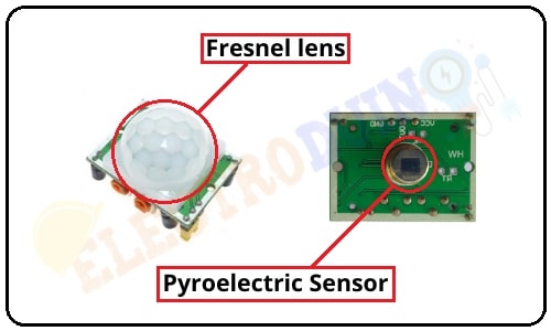
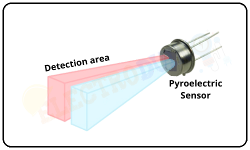
Pyroelectric Sensor | PIR mainly consists of a pyroelectric sensor, which can detect levels of infrared radiation. Pyroelectric sensors are thermal detectors that use temperature fluctuations to create a charge change on the surface of pyroelectric crystals, which produces an electrical signal. |
Fresnel lens | The pyroelectric sensor is placed behind a multifaceted lens. This lens is known as the Fresnel lens. It helps the sensor to “chops up” the view of the world into smaller cones of heightened visibility and intervening areas of lessened visibility thus widening the useful viewing /detection angle dramatically. |
Back Side Components
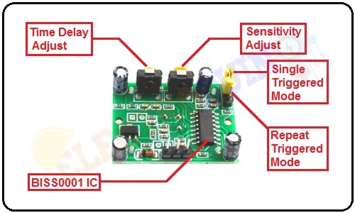
BISS0001 IC | sensors use the BISS0001 undoubtedly a lowcost CMOS chip. CMOS is a high input impedance operational amplifier. This chip takes the output of the sensor and does some minor processing on it to emit a digital output pulse from the analog sensor. |
Time Delay Adjust | This potentiometer used to set the delay time of the sensor. Counterclockwise or Left Clockwise or Right |
Sensitivity Adjust | This potentiometer used to adjust the sensitivity or distance of the sensor. Clockwise or Right Rotate the potentiometer in the clockwise direction, the sensitivity of the sensor increased, and the sensing distance increase about 7 meters. Counterclockwise or Left Rotate the potentiometer in the counterclockwise direction, the sensitivity of the sensor decreased, and the sensing distance decrease about 3 meters. |
Single Triggered Mode | In Single Triggered Mode, Output goes HIGH when any motion is detected. After a specific delay, the output goes to LOW even if the object is in motion. The delay time is set using the Time Delay Adjust potentiometer. The output is LOW for some time and again goes HIGH if the object remains in motion. In this mode, the PIR sensor must be set on LOW |
Repeat Triggered Mode | In Repeat Triggered Mode, Output goes HIGH when motion is detected. The output of the sensor is HIGH until the object is in motion. When the object stops motion or leaves from the sensor detection range, the sensor continuously provides HIGH output up to some specified delay. The delay time is set using the Time Delay Adjust potentiometer. In this mode, the PIR sensor must be set on HIGH. |
How Passive Infrared Sensor or PIR Sensor Works
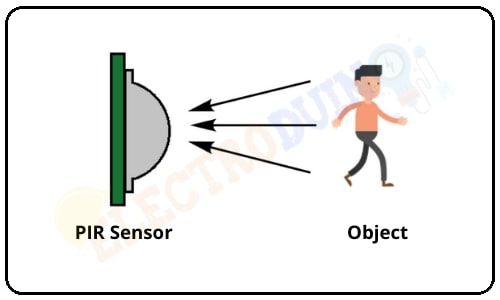
PIR Sensor module’s main component is the pyroelectric sensor, which detects levels of infrared radiation. It consists of two slots. These slots are made of a special material that helps to sense IR radiation. The input signals from both slots terminals of the PIR elements are amplified using the amplifier circuit and compared using the comparator circuit of the PIR sensor module.
Movement of the object
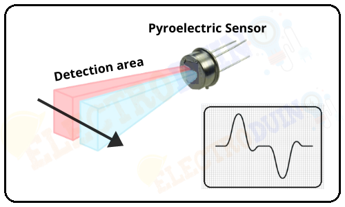
When a human, animal, or other objects passed in front of the sensor area. It intercepts one slot of the pyroelectric sensor. For this reason a positive differential change between the two slots. This change is indicated by Part A in the below figure. When a human, animal, or other objects leaves the sensor sensing area, the sensor generates negative differential change. This change is indicated by Part B in the below figure. In this case, the output of the comparator circuit is High(1). It means the output of the Sensor is High(1).
No Movement of the object
When no movement in front of the sensor range, in this situation the two slots are sensed the same amount of IR radiation. For this reason, there is no error signal between differential inputs in these slots. So the comparator circuit output is Zero(0). It means the output of the Sensor is Low(0).
Specifications
| Parameter | Value |
| Working input voltage | 4.5V to 12V (+5V recommended) |
| Output voltage | High: 3.3V TTL, Low: 0V |
| Detection angle | Approximately 120 degrees |
| Range | Adjustable, up to 7 meter |
| Operating modes | Repeatable(H) and Non- Repeatable(H) |
| Low power consumption | 65 mA |
| Operating Temperature | -20 – +80 Degrees C. |
| PCB Dimensions | 33x25mm, 14mm High not including the Lens. |
| Lens Dimensions | 11mm high, 23mmDiameter. |
| Weight | 6g |
Applications
- Detect Infrared (IR) radiation from objects
- Motion detection
- Automatic lighting system.
- Security system.