Rain Sensor Module | How it’s Works
Hello friends! Welcome back to ElectroDuino. This blog is base on What is Rain Drop Sensor Module | How Rain Drop Sensor Module Works. Here we will discuss the Introduction to Rain Sensor Module, pin diagram, Working Principle, Features, and applications.
Introduction
A rain sensor is one kind of low-cost electronic sensor which is used to detect the rainfall or water drops. It works as a switch. Normally the switch is open condition. This sensor is consists of mainly two parts, one is Sensing Pad and another one is the Sensor Module. When rainfall or water drops fall on the Sensing Pad surface, then the switch will be closed. The Sensor Module reads data from the sensor pad and processes the data and converts it into a digital/analog output. So, the sensor can provide both types of output Digital output (DO) and Analog output(AO).
Rain Drop Sensor Module Pin Diagram
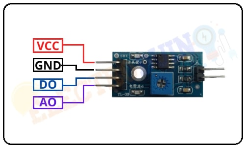
| Pin No | Pin Name | Description |
| 1 | VCC | +5 v power supply |
| 2 | GND | Ground (-) power supply |
| 3 | DO | Digital Output (0 or 1) |
| 4 | AO | Analog Output (range 0 to 1023) |
Rain Sensor Module Hardware Overview

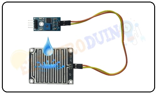
The Rain Sensor Module is consists of mainly two parts, one is Sensing Pad and another one is the Sensor Module.
-
Sensing Pad
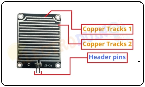
The Rain Sensor Module’s Sensing Pad consists of two nickel-coated series copper tracks. Also, it has two Header pins, these are internally connected to the two copper tracks of the Sensing Pad. These pins are used to connect the Sensing Pad to the rain sensor module circuit through two jumper wire. Always, one pin of the rain sensor circuit provides a +5v power supply to the one track of the sensing pad, and another pin is received the return power supply from another track of the sensing pad.
Normally under dry conditions, the sensing pad provides high resistance and low conductive. So, the 5v power supply cannot be passed from one track to another track. Its resistance varies according to the amount of water on the surface of the sensing pad. When water drops fall on the sensor pad surface its resistance will decrease and conductivity will increase. So, when water drops increase on the pad surface it can pass more power supply through one track to another track.
-
Sensor Module

The Sensor module is consists of some key components. These are LM393 Comparators, Variable Resistor (Trimpot), Power LED, output LED.
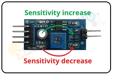
3. Variable Resistor (Trimmer)
This rain sensor module circuit has an onboard Trimpot or variable resistor(potentiometer), which is a 10k preset. It is used to set the sensitivity of the rain sensor, rotate the preset knob to adjust the sensitivity of the rain detection. If the preset knob rotated clockwise, the rain sensor sensitivity will be increased. If it rotated counterclockwise, the rain sensor sensitivity will be decreased.
4. Power LED
This LED indicates the sensor power supply is ON or OFF. When we turn on the sensor power supply this RED LED is also turn ON.
5. Output LED
When the rain sensor detects the rainfall or water drops, the RED LED is turn on. When it does not detect any rainfall or water drops, the RED LED is turn off.
How Rain Sensor Module Works
At first, we need to connect the Sensing Pad to the Sensor Module through the jumper wire. Now we can connect the rain sensor module’s Vcc & Gnd pin to 5v power supply. Then set the threshold voltage at the Non-Inverting input (3) of the IC in dry condition of the sensing pad by rotating the potentiometer knob to set the sensitivity of the sensor.
When water drops increase on the sensing pad surface then its conductivity will increase and also resistance will decrease. Then a Low amount of voltage from the sensing pad is given to the Inverting input (2) of the IC. Then the LM393 IC compares this voltage with the threshold voltage. In this condition, this input voltage is less than the threshold voltage, so the sensor output goes LOW (0).
When no water drops fall on the sensing pad surface then it has low conductivity and high resistance. Then the high amount of voltage will be allocated across the sensing pad. So, a High amount of voltage from the sensing pad is given to the Inverting input (2) of the IC. Again the LM393 IC compares this voltage with the threshold voltage. In this condition, this input voltage is greater than the threshold voltage, so the sensor module output goes High (1).
Rain Sensor Specifications
| Parameter | Value |
| Operating Voltage | 3.3V – 5V |
| Operating Current | 15 mA |
| Comparator chip | LM393 |
| Sensitivity | Adjustable via Trimpot |
| Output type | Analog output voltage (AO) and Digital switching voltage (DO) |
| LED lights indicators | Power (red/green) and Output (red/green) |
| Sensing pad | 5cm x 4 cm nickel plate on one side. |
| Module PCB Size | 3.2cm x 1.4cm |
Application
- Rainfall detection
- It’s used in an irrigation system, when rainfall is started it shut down the watering system automatically.