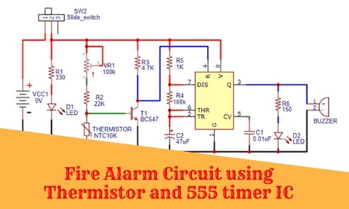
Fire Alarm Circuit using Thermistor and 555 timer IC
Hello friends! Welcome back to ElectroDuino. This blog is base on How to Make a Fire Alarm Circuit Using Thermistor and 555 timer IC. Here we will discuss Introduction to Fire Alarm Circuit, Block Diagram, components required, circuit diagram, working principle, advantages, disadvantages, and applications.
Introduction
In these days a big problem is suddenly fire accidents at building, office, bank, gas station and other property. So the fire alarm is a crucial device to detect fire at an early stage and warns people about the fire. Basically Fire alarm can be created by two logic first one is sensing smoke and another one is sensing temperature. In this project, we will learn how can design a Fire alarm circuit by 2nd logic sensing temperature. Here we use a thermistor to sense the temperature and ne555 timer IC to process the thermistor output. Let’s start this project
Project Concept
The key component of the circuit is Thermistor, transistor, 555 Timer IC and Buzzer. The thermistor is a variable resistor its resistance change according to the changing of the temperature. It is used to detect the temperature. The transistor works as a switch. It operates by the thermistor output voltage and controls the NE555 timer IC output. The NE555 timer IC works in Astable mode so it produces oscillating output for LED and buzzer. The LED and Buzzer work as an indicator. When the thermistor detects fire then the LED will turn ON and Buzzer makes sounds.
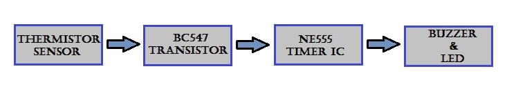
Block Diagram of Fire Alarm Circuit
Components Required
| Components Name | Quantity |
| NE555 Timer IC | 1 |
| BC547 Transistor | 1 |
| NTC 10k Thermistors | 1 |
| R1: 330 ohm Resistors | 1 |
| R2: 22 k ohm Resistors | 1 |
| R3: 4.7 k ohm Resistors | 1 |
| R4: 100 k ohm Resistors | 1 |
| R5: 1 k ohm Resistors | 1 |
| R6: 150 ohm Resistors | 1 |
| Variable Resistor 100 k ohm | 1 |
| C1: 0.01 uf Ceramic Capacitor | 1 |
| C2: 47 uf Electrolytic Capacitor | 1 |
| Buzzer | 1 |
| Red LED (D1) | 1 |
| Green LED (D2) | 1 |
| Switch | 1 |
| Battery 9v | 1 |
Tools Required
| Tools Name | Quantity |
| Soldering Iron | 1 |
| Soldering wire | 1 |
| Soldering flux | 1 |
| Soldering stand | 1 |
| Multimeter | 1 |
| Desoldering pump | 1 |
| Wirecutter | 1 |
Component Explanation
10k Thermistor
The thermistor is one type of variable resistor whose resistance change according to the change in temperature. There are two types of temperature available one is the negative temperature coefficient(NTC) and another one is the positive temperature coefficient(PTC). In this project, we will use the 10K negative temperature coefficient(NTC) thermistor. Whose, resistance is increase when the temperature is decreased and resistance is decreased when the temperature is increasing.
BC547 Transistor
BC547 is an NPN Bipolar Junction Transistor. This is normally used as a switch and amplifier. In this circuit, the transistor is used as a switch. The smaller amount of current applied at the base, it can control the larger amount of currents at the collector and emitter.
NE555 timer IC
555 Timer IC one of the most well-known and most utilized ICs ever. This IC mainly used as a time delay, oscillator, and flip-flop element in different applications and projects. The 555 timer IC has three different operating modes, these are astable modes, bistable modes, and monostable modes. So, this IC output pin can produce rectangular pulses having a specific frequency.

Buzzer and LED (D2)
The buzzer and Red LED(D2) is used as an indicator. When the thermistor detects fire then the LED will turn ON and Buzzer makes sounds.
9v power supply is used to operate this circuit and LED (D1) indicates the circuit is ON.
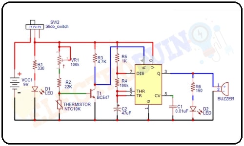
Circuit Diagram Fire Alarm using Thermistor and 555 timer IC
Working Principle Fire Alarm
The working of the Fire Alarm circuit is very simple. When the thermistor has not detected any Temperature, Therefore thermistor resistance is 10 k ohm. So sufficient voltage available across the base-emitter of the transistor, which makes it ON. In transistors, usually, 0.7v voltage is required across the Base and Emitter. As a result, 555 timer IC Pin 4 is connected to the ground, When a negative pulse is applied to pin 4 then the IC becomes reset or disable.
Similarly, When the thermistor has detected Temperature, Then thermistor resistance starts to decrease. So sufficient voltage is not available across the base-emitter of the transistor, which makes it OFF. Now, the 555 timer IC Pin 4 is disconnected to the ground and it gets positive voltage through the resistor (R3). As a result, the IC starts working and generate an output signal. Also, the buzzer & LED get voltage to operate and its start indicates.
Applications of Fire Alarm
- It can be used at buildings, offices, banks, gas stations, and other properties to avoid fire accidents.
Advantages and Disadvantages of Fire Alarm Using Thermistor
Advantages of Fire Alarm
- This circuit is low cost but high efficient
- Easy to construct the circuit
- Small circuit and portable
Disadvantages of Fire Alarm
- Very High temperature may damage the circuit.
- The thermistor sensing part must be set outside of the circuit board for better sensing.