
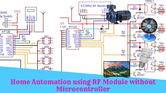
Home Automation using RF Module without Microcontroller
Hello friends! Welcome back to ElectroDuino. This blog is base on Home Automation using RF Module without Microcontroller. Here we will discuss Introduction to Home Automation using RF Module, Project Concept, Block Diagram, Components Required, Circuit Diagram, and Working Principle.
Introduction
This is a simple low-cost Home automation system using the RF module. This Home automation system is built without a microcontroller. Using this system we can control 4 electric home appliances remotely like TV, fan, lights, AC, etc. It can be controlled from up to 20 meter range.
Project Concept
In this project, we will control 4 AC home appliances using RF remote via Radio Signal communication. Here we will use Four switches to control four AC appliances wirelessly.
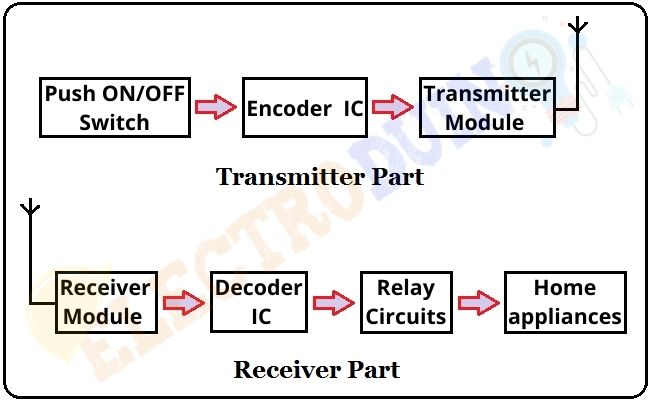
This project consists of two parts, these are transmitter and Receiver. The transmitter part consists of 4 switches, Encoder IC, and an RF transmitter module. The Encoder IC takes 4-bit data from these four push-on/off switches, when these will pressed and convert this 4-bit data into serial data, then send this data using the RF transmitter module via radio Signal.
The RF receiver module receives this serial data and sends it to the Decoder IC. Then the Decoder IC decodes this data and sends a command to the relays to controls the home appliances.
Block Diagram of Home Automation using RF Module without Microcontroller
Components Required
| Transmitter Part | |
| Components Name | Quantity |
| 433 Mhz RF Transmitter Module | 1 |
| HT12E Encoder IC | 1 |
| 1M ohm Resistor | 1 |
| Push on Push Off Switch | 4 |
| Slide Switch | 1 |
| PCB Prototyping Board | 1 |
| 9V Battery with Battery Cap | 1 |
| Connecting wire | As required in the circuit diagram |
| Receiver Part | |
| Components Name | Quantity |
| 433 Mhz RF Receiver Module | 1 |
| HT12D Decoder IC | 1 |
| 7805 Voltage Regulator | 1 |
| 0.1 uF Ceramic Capacitor | 1 |
| 33K ohm Resistor | 1 |
| Red LED |
1 |
| BC547 Transistor | 4 |
| 1K ohm Resistor | 4 |
| 1N4007 Diode | 4 |
| 5V Relay | 4 |
| 2 pin Terminal Block | 4 |
| Slide Switch | 1 |
| AC Bulb with Holder and Wire | 4 |
| PCB Prototyping board | 1 |
| 9V Battery with Battery Cap | 1 |
| 220V AC Power supply | |
| Connecting wires | As required in the circuit diagram |
Tools Required
| Tools Name | Quantity |
| Soldering Iron | 1 |
| Soldering wire | 1 |
| Soldering flux | 1 |
| Soldering stand | 1 |
| Multimeter | 1 |
| Desoldering pump | 1 |
| Wirecutter | 1 |
Circuit Diagram of Home Automation using RF Module without Microcontroller
Transmitter Part
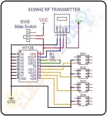
Circuit Description of Transmitter Circuit
The HT12E encoder IC’s VSS pin (9) & TE pin (14) are connected to the 9v power supply Ground (-) and the VDD pin (18) is connected to the 9v power supply VCC (+) through the Slide Switch (SW5). Encoder IC A0 – A7 pins (pin 1 – 8) are connected to the Ground(-) to set the address at 0b00000000. The Switch 1 (SW1), Switch 2 (SW2), Switch 3 (SW3), and Switch 4 (SW4) are connected to the AD11 (13), AD10 (12), AD9 (11), and AD8 (10) pin of the IC respectively. The 1M ohm (R1) resistor is connected between the OSC1 pin (15 ) and the OSC2 pin (16). The RF Transmitter module GND pin is connected to the 9v power supply Ground (-) and the VCC pin is connected to the 9v power supply VCC (+). The Data pin of the module is connected to the DOUT (pin 17) of the IC.
Receiver Part

Circuit Description of Receiver Circuit
The HT12D decoder IC VSS pin is connected to the Ground (-) of the 9v power supply and the VDD is connected to the voltage regulator Vout (+) through the Slide Switch. The decoder IC’s A0 – A7 pins (pin 1 – 8) are connected to the GND(-) to set the address at 0b00000000. The 33K ohm (R2) resistor is connected between the OSC1 pin (15 ) and the OSC2 pin (16). The LED’s Positive (+) terminal is connected to the VT pin (17) of the IC and the Negative (-) terminal is connected to the Ground (-). The RF Receiver module’s GND pins are connected to the Ground (-) and the VCC pin is connected to the Vout (+). The Data pin is connected to the DIN (pin 14) of the decoder IC.
BC547 transistors (T1, T2, T3, & T4) Emitter terminals are connected to the GND pin. Transistor-1 (T1) base terminal is connected to the data pin D11 (13) through a 1K resistor (R3), Transistor-2 (T2) base terminal is connected to the data pin D10 (12) through a1K resistor (R4), Transistor-3 (T3) base terminal is connected to the data pin D9 (11) through a 1K resistor (R5), and Transistor-4 (T4) base terminal is connected to the data pin D8 (10) through a 1K resistor (R3). Transistor 1 (T1) collector pin is connected to pin 5 of the relay 1, Transistor 2 (T2) collector pin is connected to pin 5 of the relay 2 and Transistor 3 (T3) collector pin is connected to pin 5 of the relay 3, and Transistor 4 (T4) collector pin is connected to pin 5 of the relay 4. Terminal 2 of both relays (relay 1, relay 2, relay 3 & relay 4) are connected to the +5v.
Also, you can use the 2 channel relay modules by the replacement of the relay circuit.
Working Principle of Home Automation using RF Module without Microcontroller
First of all, we need to turn on the power supply of both circuits. At the transmitter part, when all switches are in the open condition (Switch off), then the HT12E Encoder IC’ data-in pins (AD8-AD11) gets 4-bit data High value from these switches. Then the IC converts these 4-bit data into serial data and this serial data will be available at the DOUT pin (pin17) of the encoder IC. Now, this serial data is given to the RF Transmitter module, then the transmitter transmits this data through radio signals.
At the receiver part, the receiver receives this data coming from the transmitter. Then this data is given to the HT12D Decoder IC. Now the HT12D Decoder IC decodes this serial data and converts it into 4 bit parallel data and High output value available at the data-out pins (D8-D11). Then the decoder IC provides High input voltage to the BC557 PNP transistors. In this condition all relays are turned off, so all appliances are turned off.
At the transmitter part, when all switches are in the closed condition (Switch on), then the HT12E Encoder IC’ data-in pins (AD8-AD11) gets 4-bit data Low value from these switches because data-in pins are connected to the ground. Then the IC converts these 4-bit data into serial data and this serial data will be available at the DOUT pin (pin17) of the encoder IC. Now, this serial data is given to the RF Transmitter module. Then the RF transmitter module transmits this serial data using radio signals.
At the receiver part, the RF receiver module receives this serial data coming from the transmitter part. Then this serial data is given to the DIN pin (14) of the HT12D Decoder IC. Now the Decoder IC decodes this data and converts the received serial data into 4 bit parallel data and Low output value available at the data-out pins (D8-D11). Then the decoder IC provides Low input voltage to the BC557 PNP transistors. In this condition all relays are turned on, so all appliances are turned on.


