DC Motor Speed Control Using Ne555 and IRF540
Hello friends! Welcome back to ElectroDuino. This blog is based on DC Motor Speed Control with Pulse Width Modulation using Ne555 and IRF540-MOSFET. Here we will discuss Introduction to DC Motor Speed Control, Project Concept, Block Diagram, components required, circuit diagram, working principle.
Introduction
In our regular work, DC motors take an important role in several systems, like CPU fans, toy cars, Dc fans, DC drill machines, and many more appliances which are operated via a DC power supply. But most systems require us to adjust the speed of these motors manually. For example, we all have seen a small DC fan, which has a knob to control/adjust the fan speed.
In this project, we will learn How to make DC Motor Speed/RPM Control Using Pulse Width Modulation. This is a very simple and low-cost Dc Motor Speed/RPM Controller Circuit. It can save more energy. Using this circuit we can also control LED Brightness.
One question maybe comes to your mind, that we can easily control a DC motor speed using a variable resistance in series with the motor. But in this technique have a problem, it is energy wastage. It means the variable resistor dissipates the excess energy as heat. So, we have to avoid this technique.
Project Concept
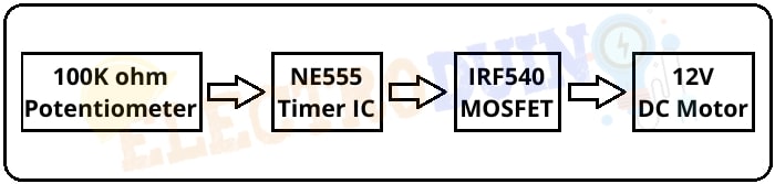
The key components of this project are Potentiometer, 555 Timer IC, IRF540 MOSFET, and 12V DC Motor. The Potentiometer is used to control the speed of the DC motors. When we will rotating the potentiometer knob then voltage change at the Trigger and Threshold Pin of the NE555 Timer IC. Then the NE555 Timer IC generates the Output voltage. This output goes to the Gate terminal of the IRF540 Mosfet. This Mosfet work as an Amplifier, which can control a large amount of voltage by applying a small amount of voltage at the Gate Terminal. This way the Mosfet will control the DC motor speed.
DC Motor Speed Control Block Diagram
Components Required
| Components Name | Quantity |
| NE555 Timer IC | 1 |
| IRF540 MOSFET(Q1) | 1 |
| 100K Potentiometer (VR1) | 1 |
| 1K ohm Resistor (R1) | 1 |
| 33 ohm Resistor (R2) | 1 |
| 10K ohm Resistor (R3) | 1 |
| 0.1uF Ceramic Capacitor (C1) | 1 |
| 0.01uF Ceramic Capacitor (C2) | 1 |
| 1N4007 Diode (D1, D2, D3) | 3 |
| 12v DC Motor (M1) | 1 |
| Slide Switch (SW1) | 1 |
| 12v Power Supply | 1 |
| PCB Zero board | 1 |
| Connecting Wire | As required in Circuit Diagram |
Tools Required
| Tools Name | Quantity |
| Soldering Iron | 1 |
| Soldering wire | 1 |
| Soldering flux | 1 |
| Soldering stand | 1 |
| Multimeter | 1 |
| Desoldering pump | 1 |
| Wirecutter | 1 |
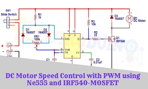
DC Motor Speed Control using Ne555 and IRF540 Circuit Diagram
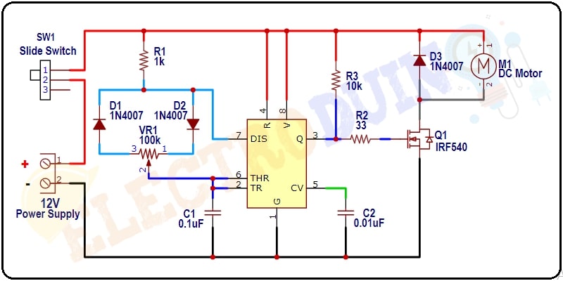
Circuit Wiring
The NE555 Timer IC Pin 8 and 4 are connected to the Positive terminal (VCC) of the power supply, and Pin 1 is connected to the Negative terminal (GND) of the power supply.
Cathode(-) terminal of the Diode 1, Anode(+) terminal of the Diode 2, and one terminal of the 1k resistor are connected together and create a junction point. This junction point is connected to Pin 7 of the IC. Anode (+) terminal of the diode 1 is connected to Terminal 3 of the Potentiometer (VR1), Cathode (-) terminal of the diode 2 is connected to Terminal 1 of the Potentiometer (VR1), and another terminal of the 1k resistor is connected to the VCC. The Signal terminal (2) of the Potentiometer is connected to Pin 6 and 2 of the IC.
One terminal of capacitor 1 is connected to Pin 6 and 2 of the IC and another one to the GND. One terminal of capacitor 2 is connected to Pin 5 of the IC and another one to the GND.
The Output Pin (3) of the IC is connected to the Gate terminal of the IRF540 Mosfet through a 33ohm resistor (R2). A 10K resistor is connected between Pin 3 and the VCC. Mosfet Source terminal is connected to the GND and Drain terminal is connected to the one terminal of the DC Motor. Another terminal of the DC Motor is connected to the VCC. Diode 3 is connected between the two terminals of DC Motor.
DC Motor Speed Control using Ne555 and IRF540 Working Principle
In this Project, the NE555 Timer IC works as an astable multivibrator. In this mode, the IC produces a continuous HIGH and LOW PWM (Pulse Width Modulation) signal from the output pin (Pin3). This Output Pulse can be adjusted by changing the value resistor and capacitor(C1), which attached to the IC. Here we used Potentiometer (VR1), so we can change the resistance value by rotating the Potentiometer (VR1) knob.
The IC’s output goes to the Gate terminal of the IRF540 MOSFET. When we will rotate the potentiometer knob then the IC’s output value also change. Here the IFR540 MOSFET works as an amplifier. The MOSFET voltage amplification change according to the voltage change at the gate terminal.
So when NE555 timer IC output voltage goes Low to High then the IFR540 MOSFET voltage Amplification rate also increases, and this amplifies voltage goes to the motor then the DC motor Speed/RPM also increase.
Similarly, when NE555 timer IC output voltage goes High to Low then the IFR540 MOSFET voltage Amplification rate will decrease, and this amplifies voltage will go to the motor then the DC motor Speed/RPM also decrease.
Not: In this circuit, we can replace the DC motor with a 12v LED. This way we can also control LED brightness.