

4×4 Matrix Keypad Module – 16 Keys | How it’s Works
Hello friends! Welcome back to ElectroDuino. This blog is base on What is 4×4 Matrix Keypad Module | How it’s Works. Here we will discuss the Introduction to 4×4 Matrix Keypad Module, pin diagram, Working Principle, Features, and applications.
Introduction
Most of the time we are used key, button, or switch to get input value in our projects. When we interface one key, button, or switch to the microcontroller then it needs one GPIO pin. But when we want to interface many keys like 9, 12 or 16, etc., then it needs many GPIO pins of a microcontroller and we will lose many GPIO pins.
Don’t worry! The 4×4 matrix keypad is a device that can solve this problem. The 4×4 matrix keypad is an input device, it usually used to provide input value in a project. It has 16 keys in total, which means it can provide 16 input values. The most interesting thing is it used only 8 GPIO pins of a microcontroller.
4×4 Keypad Module Pin Diagram
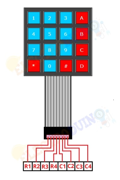
| Pin Number | Pin Name | Description |
| 1 | R1 | Taken out from 1st ROW |
| 2 | R2 | Taken out from 2nd ROW |
| 3 | R3 | Taken out from 3rd ROW |
| 4 | R4 | Taken out from 4th ROW |
| 5 | C1 | Taken out from 1st COLUMN |
| 6 | C2 | Taken out from 2nd COLUMN |
| 7 | C3 | Taken out from 3rd COLUMN |
| 8 | C4 | Taken out from 4th COLUMN |
4×4 Matrix Keypad Module Hardware Overview
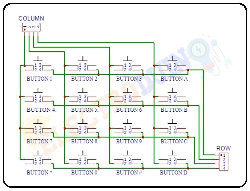
These Keypad modules are made of thin, flexible membrane material. The 4 x4 keypad module consists of 16 keys, these Keys are organized in a matrix of rows and columns. All these switches are connected to each other with a conductive trace. Normally there is no connection between rows and columns. When we will press a key, then a row and a column make contact.
How the 4×4 Matrix Keypad Module Works
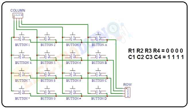
To detecting a pressed key, the microcontroller grounds all rows by providing 0 to the output pins, and then it reads the columns. If the data read from columns is = 1111, it means no key has been pressed.
When we will Pressing a button shorts one of the row lines to one of the column lines, allowing current to flow between them. For example, when key ‘Button 1’ is pressed, column 1 and row 1 are shorted.
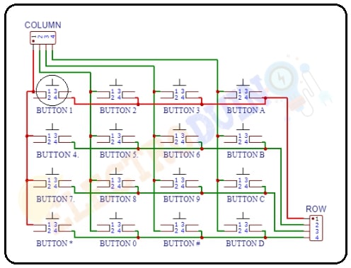
R1 R2 R3 R4 = 0 0 0 0
C1 C2 C3 C4 = 0 1 1 1
If the first column bit value is a zero, this means that the “Button1” key was pressed. For example, if C1 C2 C3 C4 = 0111, this means that a key in the C1 column has been pressed.
This process is continuing for all row & columns
How a microcontroller can read these lines for a button-pressed state
- The microcontroller sets all the column and row lines to input.
- Then, the microcontroller sets row LOW.
- After that, it checks the column lines one at a time.
- If the column connection stays HIGH, the button on the row has not been pressed.
- If it goes LOW, the microcontroller knows which row was set to LOW, and which column was detected LOW when checked.
- Finally, it knows which button was pressed that corresponds to the detected row & column.
Specifications
| Parameter | Value |
| Product type | 4 X 4 keypad module |
| Maximum Voltage rating | 24V DC |
| Maximum Current rating | 30 mA |
| Operating temp range | 32 to 122 °F (0 to 50 °C) |
| Numbers of Pin | 8 |
| Keypad Dimensions | 6.9 cm X 7.9 cm |
| Cable dimensions | 2.0 cm X 8.8 cm |
| Design | Ultra-thin |
Application
- Data entry for microcontroller
- Menu or data selection
- Password lock


