Electronic Letterbox Project using LM358 and NE555
Hello friends! Welcome back to ElectroDuino. This blog is based on the Smart Electronic Letterbox Project using LM358 and NE555. Here we will discuss Introduction to Electronic Letterbox Project, Project Concept, Block Diagram, components required, circuit diagram, working principle.
Introduction
We saw a Letterbox in front of our house, where someone drops our important letters into the box. That’s why we would need to open it every day to check if there is any letters are present inside the box. But many times we forget to check it and missed our letter. Here we will solve this problem using a simple circuit, that known as Electronic Letter Box Circuit. Here we will solve this problem using a simple circuit, that known as Electronic Letter Box Circuit. When someone drops a letter into the letterbox, then this circuit is indicated by turn on an LED and generate a Beep sound.
Project Concept
This project is consists of Laser diode, LDR, LM358 comparator IC, BC547 transistor, NE555 timer IC, LEDs, and Buzzer. The laser diode emits laser light which continuously falls on the LDR surface. When a letter will drop into the box, then this letter block the laser light and LDR detects dark. Then the LDR output voltage is changed at the LM358 IC. So the LM358 IC gives high output to the BC547 transistor. Then the transistor turn on the NE555 timer IC, which will turn on the LED (Red) and Buzzer. Here the LED and buzzer are used as an indicator, which indicates a letter present inside the box. When the letterbox is empty it is indicated by an LED (Green).
Smart Electronic Letterbox Project Block Diagram

Components Required
| Components Name | Quantity |
| LM358 comparator IC | 1 |
| NE555 Timer IC | 1 |
| BC547 Transistor | 1 |
| LDR or Light Dependent Resistor (R2) | 1 |
| 10K Potentiometer (RV1) | 1 |
| 100K Potentiometer (RV2) | 1 |
| 150 ohm Resistor (R1, R4, R5) | 3 |
| 10k ohm Resistor (R3, R6) | 2 |
| 330 ohm Resistor (R7) | 1 |
| 10uf Electrolytic Capacitor | 1 |
| 0.01uf Ceramic Capacitor | 1 |
| Laser Diode (D1) | 1 |
| Green LED (D2) | 1 |
| Red LED (D3) | 1 |
| Slide Switch (SW1) | 1 |
| Terminal Block | 1 |
| 9v Power supply | 1 |
| Connecting Wires | As required in the circuit diagram |
Tools Required
| Tools Name | Quantity |
| Soldering Iron | 1 |
| Soldering wire | 1 |
| Soldering flux | 1 |
| Soldering stand | 1 |
| Multimeter | 1 |
| Desoldering pump | 1 |
| Wirecutter | 1 |
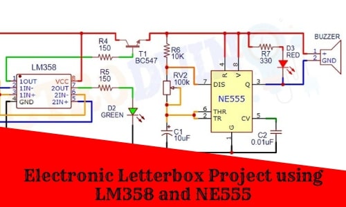
Smart Electronic Letterbox Project Circuit Diagram
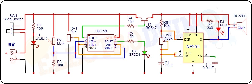
*The LM358 IC Comparator-1 inverting terminal (IC Pin 2) is connected to the junction point of LDR and resistor and 10 K potentiometer is connected at its non-inverting terminal (IC Pin 3). The LM358 IC Comparator-2 non-inverting terminal (IC Pin 5) is connected to the junction point of LDR and resistor and the 10 K potentiometer is connected at its inverting terminal (IC Pin 6). Comparator-1 output (IC Pin 1) is connected to the Positive terminal of the Green LED (D2) through a 150-ohm resistor and the Negative terminal of the Green LED (D2) is connected to the ground. Comparator-2 output (IC Pin 7) is connected to the base terminal of the BC547 transistor (T1) through a 150-ohm resistor. The transistor collector terminal is connected to the Vcc of the 9v power supply and the Emitter terminal is provide power supply to the NE555 timer IC circuit. This Transistor is used as a switch, when the transistor is active then it provides power supply to the NE555 IC to drive the LED and Buzzer.
Working Principle of Electronic Letterbox
The LM358 IC is a dual comparator IC, it has two comparators, these are comparing voltage coming from 10K Potentiometer (RV1) and LDR (R2).
The potentiometer is used to set a reference voltage at the inverting terminal (IC Pin 2) of the comparator-1 and non-inverting terminal (IC Pin 5) of the comparator-2. In other words, we can say it is used to adjust the LDR sensitivity.
Normal Condition (Empty Letterbox)
The laser diode emits laser light which continuously falls on the LDR surface. When the later box is empty, then laser light directly falls on the LDR surface. This time LDR gives High output voltage to the non-inverting terminal (IC Pin 3) of the comparator-1 and inverting terminal (IC Pin 6) of the comparator-2. Then LM358 IC’s both comparators are (comparator-1 & 2) compare this voltage to the reference voltage.
In this condition, the input voltage at the non-inverting terminal (IC Pin 3) of the comparator-1 is greater than the inverting terminal (IC Pin 2) of the comparator-1. So the comparator-1 output is High, which is tuned on the Green LED (D2). This Green LED (D2) indicated the Letterbox is empty. At the same time, the input voltage at the non-inverting terminal (IC Pin 5) of the comparator-2 is less than the inverting terminal (IC Pin 6) of the comparator-2. So the comparator-2 output is Low, which is not provide enough voltage at the base terminal of the transistor. For this reason, the transistor is in off condition, so the Red LED (D2) and Buzzer is also off.
Letter present in the Letterbox
When someone drops a letter into the later box, then this letter blocks laser light, so the laser light does not fall on the LDR surface. This time LDR gives Low output voltage to the non-inverting terminal (IC Pin 3) of the comparator-1 and inverting terminal (IC Pin 6) of the comparator-2. Then LM358 IC’s both comparators are (comparator-1 & 2) compare this voltage to the reference voltage.
In this condition, the input voltage at the non-inverting terminal (IC Pin 3) of the comparator-1 is less than the inverting terminal (IC Pin 2) of the comparator-1. So the comparator-1 output is Low, that’s why the Green LED (D2) will turned off. At the same time, the input voltage at the non-inverting terminal (IC Pin 5) of the comparator-2 is greater than the inverting terminal (IC Pin 6) of the comparator-2. So the comparator-2 output is High, which gives to the base terminal of the transistor. For this reason, the transistor will turn on. Here the BC547 transistor works as a switch. So the transistor turned on the NE555 timer IC.
Here the NE555 timer IC operated as an astable multivibrator mode. In this mode, NE555 produces a particular frequency and generates pulses in rectangular waveform output from pin3. These output pulses can be adjusted by rotating the potentiometer (RV2) knob. For this reason, the buzzer generates a continuous beep-beep sound and the Red LED (D3) starts flashing. It indicates that a letter is present inside the box.