

Smoke Detector System Using MQ2 Gas Sensor and Arduino
Hello friends! Welcome back to ElectroDuino. This blog is based on Smoke Detector System Using MQ2 Gas Sensor and Arduino. Here we will discuss Introduction to Smoke Detector System, Project Concept, Block Diagram, Components Required, Circuit Diagram, Working Principle, and Arduino Code.
Introduction
The fire accidents are the biggest problems, that’s increased day to day, which is damaged our property and puts man’s life in danger. So, Smoke Detector Systems are very useful in detecting smoke or fire in buildings, offices, banks, schools, and other Personal Properties. Which can save human life and save properties from fire accidents. In this project, we will make a low-cost Smoke Detector System Using MQ2 Gas Sensor and Arduino. This system or device continuously to measure smoke levels around it and show this level value on a display in the PPM unit. Also, it warns us by generating sound and turn on a light, when the smoke level is increased.
Project Concept
The key components of the Smoke Detector System are MQ2, Arduino board, OLED Display, LEDs, and Buzzer. The MQ2 is one type of gas sensor, which can sense Smoke as well as LPG, Alcohol, and Methane. Arduino board is the main brain of this system that controls the whole system. The MQ2 sensor continuously measures Smoke levels in the air and sends data to the Arduino board. Then Arduino prints the Smoke level value on the OLED display in the PPM unit. The LEDs and Buzzer used as indicators, it indicates the air fresh or smoke presence in the air.
Block Diagram of Smoke Detector System Using MQ2 Gas Sensor and Arduino

Components Required
| Components Name | Quantity |
| Arduino Nano | 1 |
| MQ2 Gas Sensor | 1 |
| 0.96 inch I2C OLED display | 1 |
| Green LED | 1 |
| Red LED | 1 |
| Buzzer | 1 |
| 220ohm Resistor | 2 |
| Slide Switch | 1 |
| 9V Battery with Battery connector | 1 |
| PCB Zero board | 1 |
| Connecting wires | As required in the circuit diagram |
| LED or Light Emitting Diode – Pin Diagram, Construction, Working Principle |
Tools Required
| Tools Name | Quantity |
| Soldering Iron | 1 |
| Soldering wire | 1 |
| Soldering flux | 1 |
| Soldering stand | 1 |
| Multimeter | 1 |
| Desoldering pump | 1 |
| Wirecutter | 1 |
Required Library
We need to add 2 libraries in Arduino IDE software. These are:
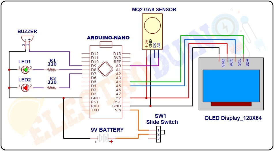
Circuit Diagram of Smoke Detector System Using MQ2 Gas Sensor and Arduino
Working Principle of Smoke Detector System Using MQ2 Gas Sensor and Arduino
When we turn on the system’s power supply, at the same time the MQ2 gas sensor starts to sense the smoke level in the air and it gives the output value to the Arduino. Then the Arduino read this output value and print it on the OLED display in the PPM unit. When the sensor sense smoke in the air, its output value goes high.
When the sensor is in the fresh air, its output value is under 400 ppm. Then the Arduino indicates it by turn on the green LED and the “Fresh Air” message is print on the Display.
When the sensor sense smoke in the air, its output value will exceed 400 PPM. Then the Arduino indicates it by turn on the Red LED and Buzzer, and the “Smoke/ Fire” message is print on the Display.
Arduino Code
 /* Air Pollution Monitoring System
    using Arduino and MQ135 Air Quality Sensor
    www.Electroduino.com
 */
 //OLED Display libraries
#include <SPI.h>
#include <Wire.h>
#include <Adafruit_GFX.h>
#include <Adafruit_SSD1306.h>

#define SCREEN_WIDTH 128    // OLED display width, in pixels
#define SCREEN_HEIGHT 64    // OLED display height, in pixels
#define OLED_RESET 4
Adafruit_SSD1306 display(SCREEN_WIDTH, SCREEN_HEIGHT, &Wire, OLED_RESET);

int SensorPin = A0;// Sensor pin connected to Analog pin "A0"
int RedLed = 7;    // Red LED pin connected to Digital pin "D7"
int GreenLed = 8;  // Green LED pin connected to Digital pin "D8"
int Buzzer = 9;    // Buzzer pin connected to Digital pin "D9"

int SensorVal = 0;

void setup()
{
  pinMode(SensorPin, INPUT); // initialize digital pin SensorPin as an input.
  pinMode(RedLed, OUTPUT);   // initialize digital pin RedLed as an output.
  pinMode(GreenLed, OUTPUT); // initialize digital pin GreenLed as an output.
  pinMode(Buzzer, OUTPUT);   // initialize digital pin Buzzer as an output.
  //Start serial communication between arduino and your computer
  Serial.begin(9600);
  //initialize with the I2C addr 0x3C (128x64)
  display.begin(SSD1306_SWITCHCAPVCC, 0x3C);
  display.clearDisplay();
  delay(10);
  // Print text on display
  display.clearDisplay();
  display.setTextSize(1);
  display.setTextColor(WHITE);
  display.setCursor(0,0);
  display.println("ELECTRODUIN0"); // Print text
  display.display();
  display.setTextSize(2);
  display.setTextColor(WHITE);
  display.setCursor(30,19);
  display.println("Smoke");
  display.display();
  display.setTextSize(2);
  display.setTextColor(WHITE);
  display.setCursor(15,35);
  display.println("Detector");
  display.display();
  delay(2000);

}


  void loop()
  {
    // Read Senso value
    SensorVal = analogRead(SensorPin);
    // Print Senso value on Serial Monitor Window
    Serial.print("Air Quality: ");
    Serial.print(SensorVal);
    Serial.println("  PPM");
    Serial.println();
    //Print Senso value or Air Quality Index on OLED Display
    display.clearDisplay();
    display.setCursor(0,0);  //oled display
    display.setTextSize(1);
    display.setTextColor(WHITE);
    display.println("Air Quality Index");
    display.setCursor(0,18);  //oled display
    display.setTextSize(3);
    display.setTextColor(WHITE);
    display.print(SensorVal);
    display.setTextSize(3);
    display.setTextColor(WHITE);
    display.println(" PPM");
    display.display();
    //delay(2000);
    // when Smoke level value less than 400PPM
    if (SensorVal<400)
     {
      digitalWrite(GreenLed,HIGH); // turn the Green LED on
      digitalWrite(RedLed,LOW);    // turn the Red LED off
      digitalWrite(Buzzer,LOW);    // turn the Buzzer off
      // Print text on OLED Display
      display.setTextSize(2);
      display.setTextColor(WHITE);
      display.setCursor(0,45);
      display.println("Fresh Air"); // Print text
      display.display();
      delay(2000);
     }
    // when Smoke level value greater than 400PPM
    else if( SensorVal>400)
     {
      digitalWrite(GreenLed,LOW);  // turn the Green LED off
      digitalWrite(RedLed,HIGH);   // turn the Red LED on
      digitalWrite(Buzzer,HIGH);   // turn the Buzzer on
      // Print text on OLED Display
      display.setTextSize(2);
      display.setTextColor(WHITE);
      display.setCursor(0,45);
      display.println("Smoke/Fire"); // Print text
      display.display();
      delay(2000);
     }
    }


