

LM358 Op-Amp IC – Pinout, Specifications
Hello friends! Welcome back to ElectroDuino. This blog is base on the LM358 Op-Amp IC. Here we will discuss the Introduction to LM358 comparator IC, IC pin diagram, Working Principle of LM358 comparator IC, Features, LM358 IC Equivalent IC, advantage and it’s applications.
Introduction
The LM358 is one type of dual-channel operational amplifier (Op-Amp). This Op-Amp IC designed and introduced by the national semiconductor. It consists of two independent, high-gain, frequency-compensated operational amplifiers (Op-Amp). The IC is designed like that the Op-Amps are operating from a single supply or split supplies over a wide range of voltages. The IC’s each op-amp can handle 3-32V DC supply & current up to 20mA. This is an 8 pin IC available in different packages. The LM358 IC available in four different types of packages, these are DSBGA, PDIP, TO-CAN, and SOT-23(5). But the 8 pin PDIP package is most used. These IC are used in op-amp circuits, DC gain blocks, and transducer amplifiers.
Op-Amp LM358 IC Internal Structure
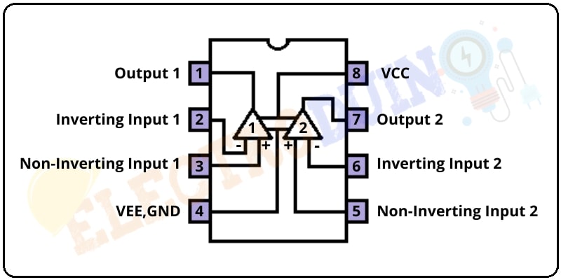
The LM358 comparator IC consists of two inbuilt operational amplifiers (Op-Amp).
The Op-Amp 1 & Op-Amp 2 negative inputs are connected to IC pin 4 and positive inputs are connected to IC pin 8.
The Op-Amp 1 Inverting input is connected to IC pin 2 and the Non-Inverting input is connected to IC pin 3. The output of the Op-Amp 1 is connected to IC pin 1.
The Op-Amp 2 Inverting input is connected to IC pin 6 and the Non-Inverting input is connected to IC pin 5. The output of the Op-Amp 1 is connected to IC pin 7.
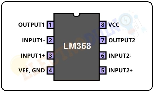
Op-Amp LM358 Pin Configuration/Pinout
| Pin Number | Pin Name | Description |
| 1 | OUTPUT1 | This is the output pin of the Op-Amp 1 |
| 2 | INPUT1- | Inverting Input pin of Op-Amp 1 |
| 3 | INPUT1+ | Non-Inverting Input pin of Op-Amp 1 |
| 4 | GND | This is the Ground pin of the IC. it needs to connect to the Negative(-) terminal of Supply Voltage. |
| 5 | INPUT2+ | Non-Inverting Input pin of Op-Amp 2 |
| 6 | INPUT2- | Inverting Input pin of Op-Amp 2 |
| 7 | OUTPUT2 | This is the output pin of the Op-Amp 2 |
| 8 | VCC | This is the positive pin of the IC. it needs to connect to the Positive(+) terminal of Supply Voltage. |
Working Principle
First of all, we need to connect the power source with the Vcc and GND pin of the LM358 IC to activate the IC. Then, we need to provide two input voltage to the Op-Amp for comparison. Now, we can get an output from the Op-Amp.
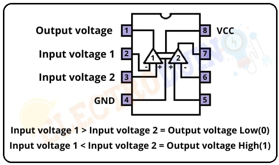
As an example, here we used the Op-Amp1 of the LM358 IC to get output. First of all, we provide input voltage 1 to the Inverting terminal (Pin2) and input voltage 2 to the Non-Inverting Terminal (Pin3).
If the input voltage 1 is greater than the input voltage 2, then the output of the op-amp will be drawn down to the ground, which means the output voltage is Low (GND).
If the input voltage 1 is less than the input voltage 2, then the output of the op-amp stays at VCC, which means the output voltage is HIGH (VCC).
Similarly, we can get output from Op-Amp 2.
Features of LM358 IC
| Parameter | Value |
| Single power supply Range | 3V to 32V DC |
| Dual power supplies Range | + or -1.5V to + or -16V |
| Supply Drain Current | 500 μA |
| Input Offset Voltage | 2mV |
| DC gain of the IC | 100dB |
| Operating ambient temperature | – 0˚C to 70˚C |
| Soldering pin temperature | – 260 ˚C (for 10 seconds – prescribed) |
| Available Package | TO-99, CDIP, DSBGA, SOIC, PDIP, DSBGA |
LM358 IC Equivalents IC
LM258, LM324, LM2904A, LM2904V, NCV2904
Advantages of LM358 IC
- Operated by single supplies.
- Two operational amplifiers of this IC are compensated internally.
- Compatibility with all types of logic.
- direct sensing near to GND and VOUT.
- Power drain suitable for the operation of the battery.
Applications
- Small Signal Amplification
- Digital multimeters, Oscilloscopes
- Loop control & regulation
- Sensor Circuits
- DC gain blocks.
- Transducer amplifiers.
- General signal amplification.
- Active filters.
- Operational amplifier circuits.
- Conventional op-amp circuits
- Integrator, Differentiator, Summer, adder, Voltage follower, etc.


