
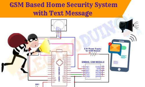
GSM Based Home Security System using PIR Sensor and Arduino
Hello friends! Welcome to ElectroDuino. This blog is based on GSM Based Home Security System using Arduino, PIR Motion Sensor, and SIM800 GSM Module. Here we will discuss Introduction to Home Security System, Project Concept, Block Diagram, Components Required, Circuit diagram, Working Principle, and Arduino Code.
This project is sponsored by pcbway.com. It’s a Professional grate PCB prototype service company. They are providing you 10 high-quality PCBs at only 5$. At first register on the website, then fill in all the specifications like Dimensions, Layers, Thickness, color, and Quantity. In the last upload your Gerber files and place your Order Now. After completing all the processes, they produce your PCB prototype within 24 hours.
So, order now to get high-quality PCB prototype quickly from pcbway.com
Introduction
In our day-to-day life crime is increasing rapidly, so one of the important things is the security of our home, office, and shop from thieves/burglars. There are different types of home security systems available in the market including several security features like fire, LPG, electronic door lock, heat, smoke, temperature, etc.
In this project tutorial, we will be going to design a Home Security System using PIR sensor and GSM module which detects intruders and informs the owner. This system/device detects thieves/burglars when they try to enter the house and informs the owner by sending text messages on her/his phone.
For this project you should know:
- HC-SR501 (Passive Infrared) PIR Sensor | How it’s Works
- Interfacing PIR Sensor with Arduino | Motion Detector using PIR Sensor
- SIM800l GSM Module, Pinout/Pin Diagram, Hardware Overview, Features, Power Supply, and applications.
Project Concept
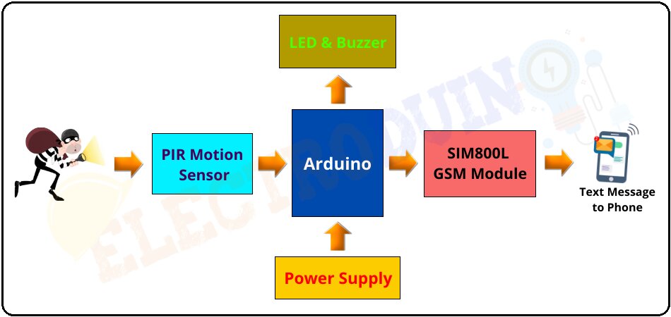
This GSM Based Home Security System project has been implemented on a very simple concept and it’s very easy to build. The fundamental components of this project are the PIR sensor, Arduino, SIM800L GSM Module, LED, and Buzzer.
PIR sensor detects the motion of surrounding objects by sensing the difference in infrared or radiant heat levels emitted by that objects. It produces high output by detecting the movement of any objects or human body in front of it. Here it is used to detect thieves/burglars (any human beings). When someone comes in front of the sensor, it detects motion and provides a high output voltage. This output voltage goes to the Arduino. Here we will use Arduino UNO which is the main microcontroller of this project, it controls the whole system. When the Arduino read this high output voltage, then it sends commands to the GSM module for sending a Text Message/SMS to a specific user’s Mobile number. The LED and Buzzer are working as warning indicators, which alert us when someone tries to enter the house.
Block Diagram of GSM SIM800L Based Home Security System
Components Required
| Components Name | Quantity |
| Arduino Uno | 1 |
| PIR Motion Sensor | 1 |
| SIM800L GSM Module | 1 |
| Red LED (D1) | 1 |
| Buzzer (B1) | 1 |
| 1000µf 50V Capacitor | 1 |
| Slide Switch (SW1) | 1 |
| 9V Battery with Battery connector | 1 |
| 4.1V Power Supply | 1 |
| PCB Zero board | 1 |
| Connecting wires | As required in the circuit diagram |
Tools Required
| Tools Name | Quantity |
| Soldering Iron | 1 |
| Soldering wire | 1 |
| Soldering flux | 1 |
| Soldering stand | 1 |
| Multimeter | 1 |
| Desoldering pump | 1 |
| Wirecutter | 1 |
Circuit/Schematic Diagram of GSM SIM800L Based Home Security System
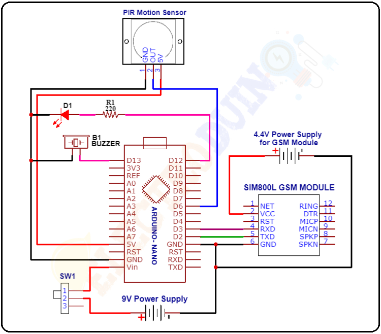
Circuit Wiring
| Components Name | Components Pin | Arduino Pin |
| PIR Motion Sensor | GND | GND |
| OUT | D6 | |
| VCC | 5V | |
| SIM800L GSM Module | VCC | * The positive terminal of 4.1V External Power Supply |
| RXD | D3 | |
| TXD | D2 | |
| GND | * The negative terminal of 4.1V External Power Supply and Arduino GND | |
| Buzzer (B1) | Positive terminal | D13 |
| Negative terminal | GND | |
| LED (D1) | Positive terminal | D12 |
| Negative terminal | GND | |
| 9V Power Supply | Positive terminal | Vin |
| Negative terminal | GND |
Working Principle of GSM Based Home Security System using Arduino
After connecting all components according to the circuit diagram and uploading the code to the Arduino board. When the input power supply is applied to the circuit, then the Arduino starts working step by step according to the code/Program.
First of all, the Arduino makes the connection to the Network with help of the SIM800L GSM Module.
At the same time, The PIR sensor requires a “warm-up” time of 20 to 60 seconds to proper operation. This time is required because the PIR sensor has a settling time duration, during this time it calibrates according to the environment and stabilizes the infrared detector.
Remember that, during this time a small motion in front of the sensor can create an error in calibration and the PIR sensor may not produce a reliable output. So, try to avoid very little movement in front of the sensor at the “warm-up” time.
We need to install the GSM Based Home Security System circuit/device at the entrance of the house, where have a chance to enter the thieves/burglars.
When someone comes in the detection range of the PIR Motion Sensor, then it detects motion and produces a High (5v) output signal from its output pin. The Arduino reads this high output signal and it realizes someone has come in front of the sensor. Now, the Arduino communicates with the SIM800L GSM module via serial communication to send Text Messages to the owner’s mobile number. The mobile number has pre-programmed in code, you can change it in code.
At the same time, the Red LED and buzzer also turn on, these warn the owner that someone (thieves/burglars) has come in front of the Door (Sensor).
Arduino Code
/*GSM SIM800L Based Home Security System using Arduino and PIR Sensor
 Electroduino.com = https://www.electroduino.com/ */

#include <SoftwareSerial.h>
SoftwareSerial mySerial(3, 2);//Arduino's (rx,tx)

int PIRsensor = 6; //PIR Sensor Pin
int RedLED = 12;     // Red LED pin
int buzzer = 13; //Buzzer Pin

int MotionRead, Motion_alert_val,recheckMotion;
int pir_Status, Motion_sms_count=0, PIR_Motion_Status;

 void setup()
 {
  pinMode(PIRsensor, INPUT);
  pinMode(RedLED, OUTPUT);
  pinMode(buzzer, OUTPUT);
  Serial.begin(9600);

  mySerial.begin(9600);  // Sim Baud rate
  Serial.println("Initializing...");
  delay(1000);
  mySerial.println("AT"); //Once the handshake test is successful, it will back to OK
  updateSerial();

  digitalWrite(RedLED, LOW);    // Red LED off
  digitalWrite(buzzer, LOW);    // Buzzer off
 }

 void loop()
 {
  CheckMotion();
  CheckNoMotion();
 }


 void CheckMotion()
  {
   Serial.println("Motion Scan - ON");
   Motion_alert_val = ScanMotion();

   //D6 Pin becomes HIGH when Motion detected
   if (Motion_alert_val == HIGH)
    {
     MotionAlert(); // Function to send SMS Alerts
    }
  }
  int ScanMotion()
   {
    MotionRead = digitalRead(PIRsensor); // reads the Gas sensor D0 Pin
    return MotionRead; // returns temperature value in degree celsius
   }

 // Function to send SMS Alerts
 void MotionAlert()
  {
   digitalWrite(RedLED, HIGH); // Red LED on
   digitalWrite(buzzer, HIGH); // Buzzer on
   delay(9000);

   while (Motion_sms_count < 2) //Number of SMS Alerts to be sent
   {
     mySerial.println("AT+CMGF=1"); // Configuring TEXT mode
     updateSerial();
     mySerial.println("AT+CMGS=\"+91xxxxxxxxxxx\"");//change ZZ with country code and xxxxxxxxxxx with phone number to sms
     updateSerial();
     mySerial.print("Alert Alert!! Motion Detected !! Someone try to enter the house!! Electroduino.com "); //text content
     updateSerial();
     mySerial.write(26);

     mySerial.println("AT+CMGF=1"); // Configuring TEXT mode
     updateSerial();
     mySerial.println("AT+CMGS=\"+91xxxxxxxxxxx\"");//change ZZ with country code and xxxxxxxxxxx with phone number to sms
     updateSerial();
     mySerial.print("Alert Alert!! Motion Detected !! Someone try to enter the house!! Electroduino.com !!"); //text content
     updateSerial();
     mySerial.write(26);

     Motion_sms_count++;
    }
   PIR_Motion_Status = 1;
   Serial.println("Motion Detected! SMS Sent!");
   delay(100);
  }


 void CheckNoMotion()
  {
   if (PIR_Motion_Status == 1)
    {
     recheckMotion = ScanMotion();
     if (recheckMotion == LOW) //D0 Pin becomes HIGH when No Gas
      {
        Serial.println("No Motion Detected");
        digitalWrite(buzzer, LOW);
        Motion_sms_count = 0; //Reset count for next alert triggers
        PIR_Motion_Status = 0;
      }
    }
  }

 void updateSerial()
  {
   delay(500);
   while (Serial.available())
    {
     mySerial.write(Serial.read());//Forward what Serial received to Software Serial Port
    }
   while(mySerial.available())
   {
    Serial.write(mySerial.read());//Forward what Software Serial received to Serial Port
   }
  }


