

Voice Controlled Home Automation using Arduino and HC-05 Bluetooth Module
Hello friends! Welcome back to ElectroDuino. This blog is base on Voice Controlled Home Automation using Arduino and HC-05 Bluetooth Module. Here we will discuss Introduction to Voice Controlled Home Automation, Project Concept, Block Diagram, Components Required, Circuit Diagram, Working Principle, and Arduino code.
Introduction
In the previous Home Automation Series, we have learned how to make RF Based, IR Remote Control, Bluetooth Control, and GSM Based home automation systems, where we have controlled home appliances by sending text messages or pressing the button. But, in this project, we will control the AC home appliances by sending Voice Command from our smartphone. We will use a Bluetooth module in our project that helps to connect and communicate with a smartphone wirelessly. Also, we will use a Bluetooth app on our smartphone, which is helping to send our voice Command from our smart phone to the project circuit.
Project Concept
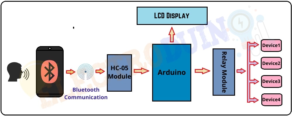
Here we will control four different home appliances by voice Command. The key components of this project are Arduino, Bluetooth module, Relay module, LCD display, a smartphone, and Android App. At first, we need to install the app on our smartphone, which is easily available in the play store. This app receives our Voice command and sends it to the Bluetooth module wirelessly. The Arduino decodes this command from the Bluetooth module. Then Arduino sends a command to the Relays to control the home appliances. These four home appliances are switched on/off by eight different voice commands. The LCD module will display the status of the home appliances on or off.
Block Diagram of Voice Controlled Home Automation
Components Required
| Components Name | Quantity |
| Arduino ( you can use Arduino nano or other types of Arduino board) | 1 |
| HC-05 Bluetooth Module ( you can use the HC-06 Bluetooth Module circuit diagram and the connection is the same) | 1 |
| 4 Channel Relay Module | 1 |
| LCD display module |
1 |
| AC Bulb with Holder and Wire | 4 |
| PCB Prototyping board | 1 |
| 12V DC Power supply | 1 |
| 220V AC Power supply | 1 |
| Connecting wires | As required in the circuit diagram |
| Android Phone | 1 |
| “Bluetooth voice control for Arduino” App | Available in the play store |
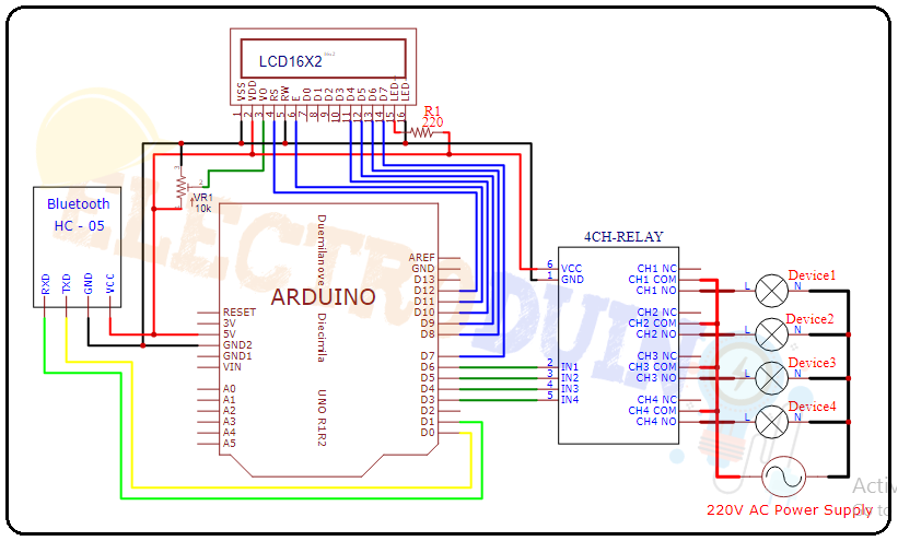
Circuit Diagram of Voice Control Home Automation using Arduino and Bluetooth Module HC-05
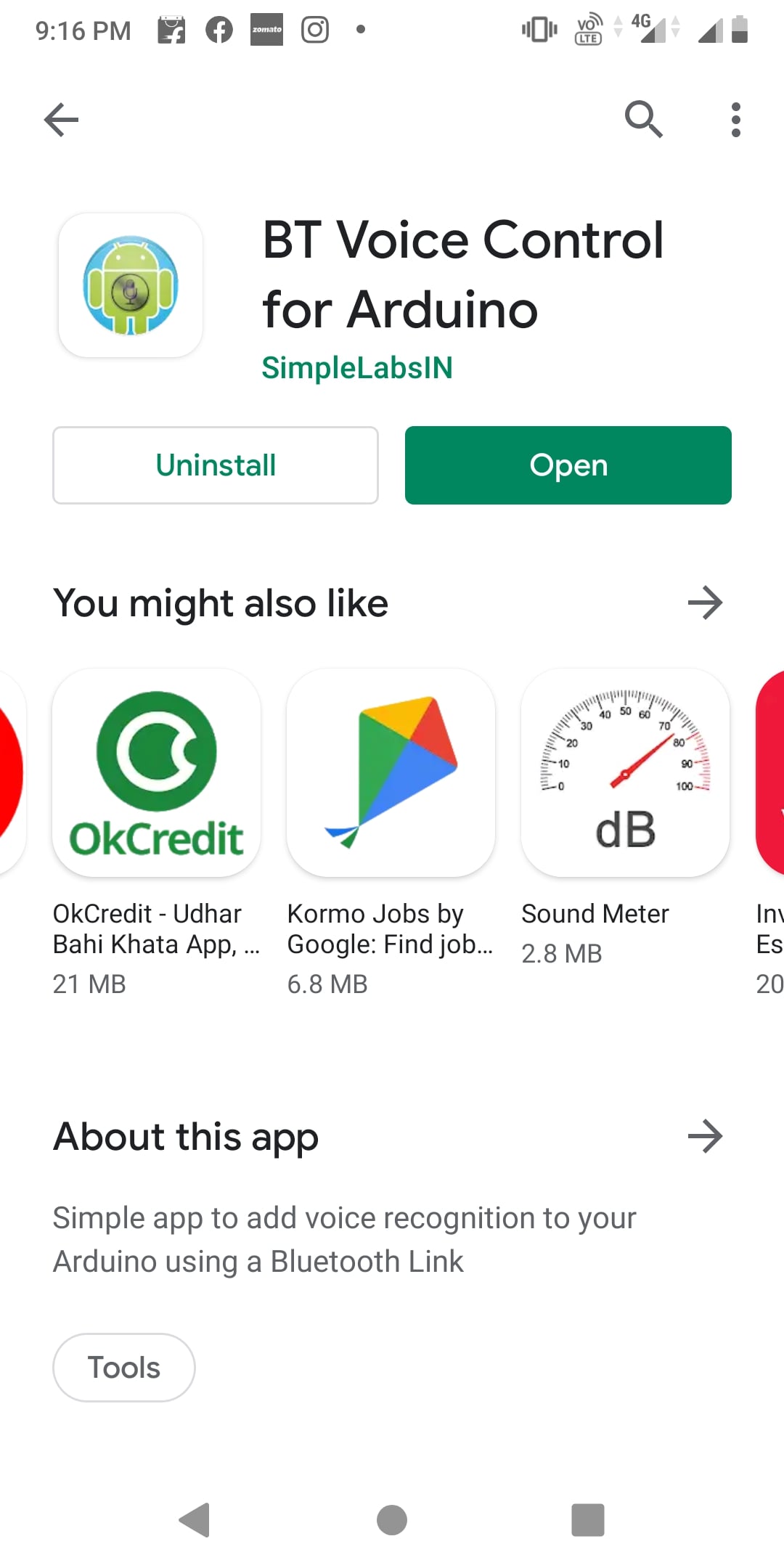
App Configure
First of all, open the Play Store of your phone and search for “BT Voice Control for Arduino”. Then you will get this app. Now install this app.
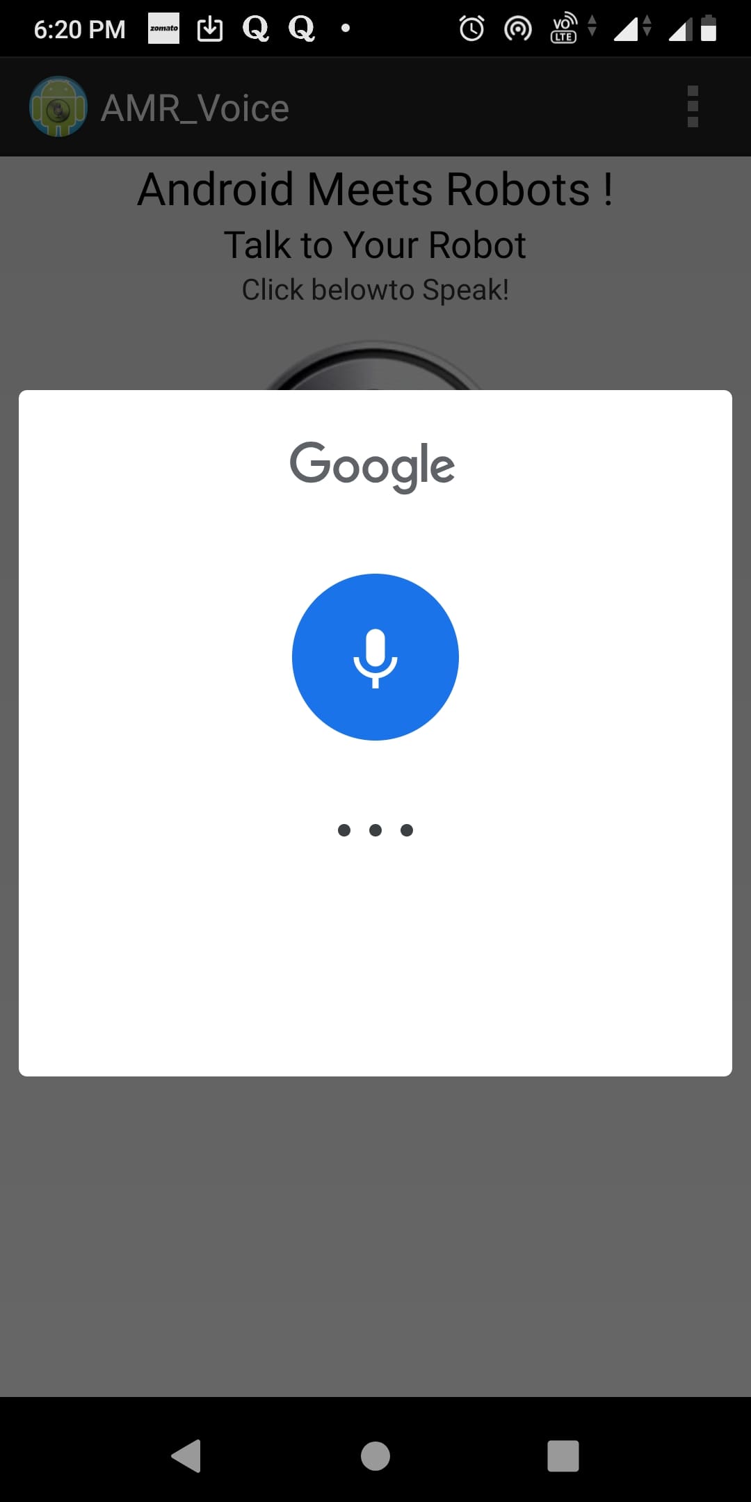
After completing the installation process, open the app and make sure the circuit is connected to the power supply and the Bluetooth module is on. Now click on the mic button to come on the app dashboard.

Now you can see the 3 dots on the top right corner of the app dashboard. Then click on it and select the Connect Robot option. Before doing this make sure, your smartphone has Paired with Bluetooth Module. If it not paired then find the HC-05 Bluetooth module in your phone Bluetooth settings and pair your phone with it. In this case, the HC-05 Bluetooth module asks for a pin code for pairing, usually, the pin code is 1234 or 0000.

After click on the Connect Robot option. Then select the HC-05 for connecting the Bluetooth module with your phone. When this process is successfully completed, then you get the “Connected to HC-05” message on the app dashboard.


Now click on the mic button on the dashboard, then you can send a voice command through the App.
Working Principle of Voice Control Home Automation using Arduino and Bluetooth Module HC-05
At first, we need to choose 8 different types of Voice Commands to control 4 devices. Particular two voice commands are used to control a device. For example, the “turn on light ” command is used to Turn ON the Light, and the “turn off light ” command is used to Turn OFF the Light. These Voice commands are used in Arduino code. The list of voice commands is below, which is used in Arduino code:
| Voice commands | Device status | Control Relay (Relay Pin) |
| turn on light | Light On | Relay-1 (IN1) |
| turn off light | Light Off | |
| turn on fan | Fan On | Relay-2 (IN2) |
| turn off fan | Fan Off | |
| turn on TV | TV On | Relay-3 (IN3) |
| turn off TV | TV Off | |
| turn on pump | Pump On | Relay-4 (IN4) |
| turn off pump | Pump Off | |
| turn on all | All Device On | Relay-1, Relay-2 Relay-3, Relay-4 (IN1, IN2, IN3, IN4) |
| turn off all | All Device Off |
When we send a voice command through the App, then the Bluetooth module receives that command and passes it to the Arduino. Now Arduino compares this command with the predefine Commands (which are defined in Arduino code). If this command matches then Arduino sends a command to operate the relay module. We can see the Device status (on or off) on the 16×2 LCD Display Module.
For example, when we send the “turn on light” voice command through the app. Then the Arduino gets this command through the Bluetooth module. Then the Arduino sends Low (0) input voltage to the Input-1 (IN1) pin of the relay module. Now the relay is in On mode. So the device (light) will also turn on, which is connected to the relay-1 of the relay module. At the same time, the “D1 (Device 1) is ON” status print on the 16×2 LCD Display Module.
When we send the “turn off light” voice command through the app. Again the Arduino gets this command through the Bluetooth module. This time the Arduino sends a High (5v) input voltage to the Input-1(IN1) pin of the relay module. Now the relay is in Off mode. So the device (light) will also turn off, which is connected to the relay-1 of the relay module. At the same time, the “D1 (Device 1) is OFF” status print on the 16×2 LCD Display Module.
In this way, we can control all relays of the 4 channel Relay module through the voice command
Arduino Code for Voice Controlled Home Automation
//libraries for LCD Display
#include <LiquidCrystal.h>
// Define LCD display pins
LiquidCrystal lcd(12,11,10,9,8,7);
// DeUfine 4 channel relay pins
const int Light = 6; // Relay pin 1 (IN1)
const int Fan = 5;   // Relay pin 2 (IN2)
const int TV = 4;    // Relay pin 3 (IN3)
const int Pump = 3;  // Relay pin 4 (IN4)

String data; //Variable for storing received data

 void setup()
  {
   Serial.begin(9600); //Sets the baud for serial data transmission
   // Set Relay pins as OUTPUT
   pinMode(Light, OUTPUT);
   pinMode(Fan, OUTPUT);
   pinMode(TV, OUTPUT);
   pinMode(Pump, OUTPUT);
   // Print massage on LCD Display
   lcd.begin(16, 2);
   lcd.setCursor(0,0);
   lcd.print("Voice Controlled");
   lcd.setCursor(0,1);
   lcd.print("Home Automation");
   delay(2000);
   // All devics are Off when system is on
   digitalWrite(Light, HIGH);
   digitalWrite(Fan, HIGH);
   digitalWrite(TV, HIGH);
   digitalWrite(Pump, HIGH);
   // Print Device status (all Off) on LCD Display
   lcd.clear();
   lcd.setCursor(0,0);
   lcd.print(" D1  D2  D3  D4 ");
   lcd.setCursor(0,1);
   lcd.print("OFF OFF  OFF OFF");

  }

 void loop()
  {
    // Read data from Bluetooth Module
    char ch=0;
    data="";
    while(1)
    {
      while(Serial.available()<=0);
      ch = Serial.read();
      if(ch=='#')
      break;
      data+=ch;
    }

 // Print Bluetooth Module data on serial monitor
   Serial.print(data);
   Serial.print("\n");

// Control the devices using voice command
    if (data == "*turn on light") // turn on Device1
    {
      digitalWrite(Light, LOW);
      lcd.setCursor(0,1);
      lcd.print("ON ");
      delay(200);
    }

  else if (data== "*turn off light") // turn off Device1
    {
      digitalWrite(Light, HIGH);
      lcd.setCursor(0,1);
      lcd.print("OFF");
      delay(200);
    }

  else if (data== "*turn on fan" ) // turn on Device2
    {
     digitalWrite(Fan, LOW);
     lcd.setCursor(4,1);
     lcd.print("ON ");
     delay(200);
    }

  else if (data== "*turn off fan" ) // turn off Device2
    {
     digitalWrite(Fan, HIGH);
     lcd.setCursor(4,1);
     lcd.print("OFF");
     delay(200);
    }
  else if (data== "*turn on TV" ) // turn on Device3
    {
      digitalWrite(TV, LOW);
      lcd.setCursor(9,1);
      lcd.print("ON");
      delay(200);
    }
  else if (data== "*turn off TV" ) // turn off Device3
    {
     digitalWrite(TV, HIGH);
     lcd.setCursor(9,1);
     lcd.print("OFF");
     delay(200);
    }
  else if (data== "*turn on pump" ) // turn on Device4
    {
      digitalWrite(Pump, LOW);
      lcd.setCursor(13,1);
      lcd.print("ON    ");
      delay(200);
    }
  else if (data== "*turn off pump" ) // turn off Device4
    {
      digitalWrite(Pump, HIGH);
      lcd.setCursor(13,1);
      lcd.print("OFF");
      delay(200);
    }

  else if (data== "*turn on all" ) // turn on all Device
    {
      digitalWrite(Light, LOW);
      digitalWrite(Fan, LOW);
      digitalWrite(TV, LOW);
      digitalWrite(Pump, LOW);
      lcd.setCursor(0,1);
      lcd.print("ON  ON   ON  ON ");
      delay(200);
    }
  else if (data== "*turn off all" ) // turn off all Device
    {
      digitalWrite(Light, HIGH);
      digitalWrite(Fan, HIGH);
      digitalWrite(TV, HIGH);
      digitalWrite(Pump, HIGH);

      lcd.setCursor(0,1);
      lcd.print("OFF OFF  OFF OFF");
      delay(200);
    }
 }


