

Laser Security System with Police Siren Circuit
Hello friends! Welcome back to ElectroDuino. This blog is base on Laser Security System with Police Siren Circuit. Here we will discuss Introduction to Laser Security System, Project Concept, Block Diagram, components required, circuit diagram, working principle.
Introduction
In these modern days, the security system is the most essential device, which helps us to save our house, building, shop, and office from robbery. That’s why everyone needs to use a security system in their property. In this project, we will design a low-cost Security system that will secure our property. This is a new type of leaser security system project, it has Police Siren, which will confuse the thief. In this circuit, we can also control the time duration of the police siren.
Project Concept
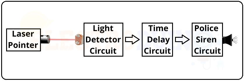
This project looks very complicated but it is divided into four simple parts. In the first part has a laser pointer, it is the main source of light in this project, which can emit light output of less than 1 mW power. This laser light continuously falls on the LDR of the light detector circuit, it is the second part of this circuit. The light detector circuit output will be change when someone crosses between the laser light and the LDR. This output change gives to the time delay circuit, it is the third part of this circuit. Using the time delay circuit we can set the time duration of sound-generating the police siren. The police siren generator circuit generates loud sounds like a police car using a speaker, it is the last and fourth part of the circuit.
Block Diagram Laser Security System with Police Siren Circuit
Components Required
| Components Name | Quantity |
| LM358 Op-Amp IC (U1) | 1 |
| NE555 Timer IC (U2, U3, U4) | 3 |
| BC547 Transistor (T1, T2) | 2 |
| Laser Pointer | 1 |
| LDR (R1) | 1 |
| 10K Potentiometer (RV1) | 1 |
| 100K Potentiometer (RV2) | 1 |
| 10K ohm Resistors (R2, R4, R6, R9) | 4 |
| 220 ohm Resistors (R3) | 1 |
| 22K ohm Resistors (R5) | 1 |
| 68K ohm Resistors (R7) | 1 |
| 4.7K ohm Resistors (R8) | 1 |
| 220K ohm Resistors (R10) | 1 |
| 220μF Electrolytic capacitor (C1) | 1 |
| 0.01μF Ceramic Capacitor (C2, C5) | 2 |
| 10μF Electrolytic capacitor (C3, C6) | 2 |
| 0.1μF Ceramic Capacitor (C4) | 1 |
| 8 ohm mini Speaker | 1 |
| Slide Switch (SW1) | 1 |
| Terminal Block | 1 |
| 9V Power Supply | 1 |
| PCB board | 1 |
| Connecting Wire | As required in the circuit diagram |
Tools Required
| Tools Name | Quantity |
| Soldering Iron | 1 |
| Soldering wire | 1 |
| Soldering flux | 1 |
| Soldering stand | 1 |
| Multimeter | 1 |
| Desoldering pump | 1 |
| Wirecutter | 1 |
Laser Security System with Police Siren Circuit Diagram
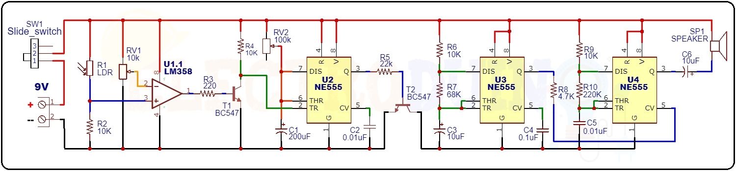
How Laser Security System with Police Siren Circuit Works
First of all, we need to place the LDR pointer in front of the LDR, So that the laser light always falls on the LDR surface.
The LDR output is connected to the inverting terminal of the LM358 comparator IC. The 10 k potentiometer signal pin is connected to the non-inverting terminal of the LM358 comparator IC, we need to set a threshold voltage by rotating the potentiometer knob. This set the sensitivity of the LDR.

When someone crosses between the laser light and LDR. So, there does not sufficient light on the LDR surface, then LDR gives low input voltage to the comparator IC. This input voltage is less than the threshold voltage. So, the LM358 IC output goes high. Here the BC547 transistor (T1) works as a switch. When the output voltage of the IC gives to the base terminal of the transistor (T1), then the transistor is in turn on.
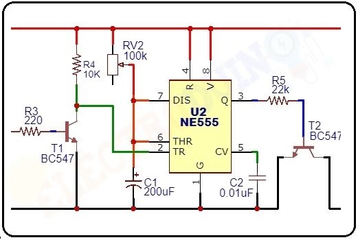
Now the terminal 2 of the NE555 IC will be connected to the ground and this gets triggered. Here this NE555 timer IC work in monostable mode. That’s why the IC output goes High for a fixed time. The output time period depends on the RV1 potentiometer and C1 capacitor. The formula of the Time Period calculation is T=1.1xRxC, where T is the Time Period, R is the potentiometer resistance value and C is the C1 capacitor. Here we can change the Time Period by rotating the potentiometer knob. This high output goes to the BC547 transistor (T2) base terminal, so this transistor also turns on. Then this transistor activates the police siren circuit.
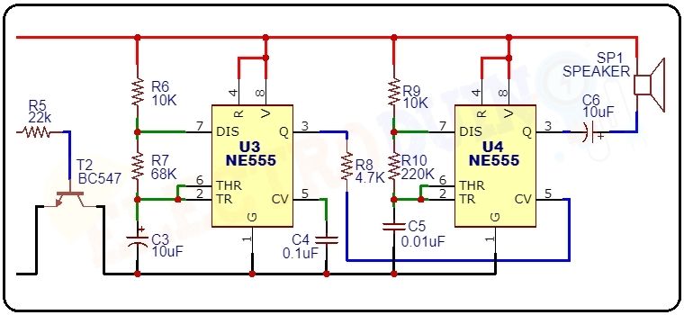
In the police siren circuit, the first NE555 timer IC works in an astable multivibrator mode. In this mode, the timer IC produces a low signal frequency from the output pin 3, this frequency is about 1 Hz. this frequency value can be changed by R6, R7, and C3. Then, this output signal frequency gets into pin 5 of the second NE555 timer IC through the R8 resistor. Now, this frequency combines with the second IC’s frequency. Then the second IC produces a mixed frequency from the output pin 3, this frequency is about 440 Hz – 550 Hz. This output goes to the speaker through a capacitor and the speaker generates a loud sound with a police siren sound effect.


