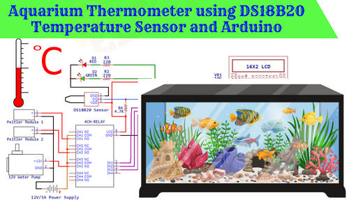
Aquarium Thermometer with Water Temperature Controller
Hello friends! Welcome back to ElectroDuino. This blog is based on the Aquarium Thermometer with Water Temperature Controller using DS18B20 Temperature Sensor and Arduino. Here we will discuss Introduction to Aquarium Thermometer with Water Temperature Controller, Project Concept, Block Diagram, Components Required, Circuit Diagram, Working Principle, and Arduino Code.
Introduction
If you want to enjoy observing fish and other marine life, you should be purchased an aquarium. An aquarium is a container (such as a glass tank) or an artificial pond where different species of fish are preserved. It increases the beauty of any place because it contains many fishes having attractive body colors and feathers. Most of people around the world like to own their home aquarium. You can see an aquarium at home, offices, hotels, and many tourist places. But this aquarium needs proper care to preserve fish or other aquatic animals. We must make sure that the water has good quality and the temperature of the water should be appropriate for the particular species of fish that live in the aquarium. One of the biggest problems with aquariums is the water temperature is changing according to the changing of the climate. Most of the fish grow well at temperatures from 23°-27° Celsius (75°-80° degrees Fahrenheit), but the needs of specific fish can vary. To maintain the water temperature we have to check and change the water daily basis. That is very reasonable work but in this busy life many times we forgot about it, which can harm the fish.
To overcome this problem in this project we will learn how to make an Aquarium Thermometer with a Water Temperature controller using Arduino. This device continuously measures the water temperature and shows the temperature values on a display. When it detects the change in water temperature (temperature increase or decrease) then it controls the temperature and again brings it back to normal temperature.
Project Concept
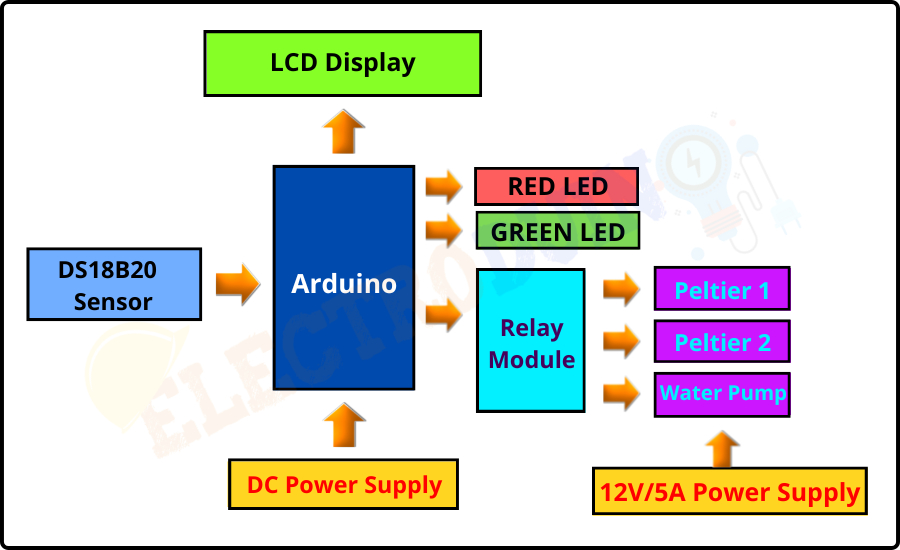
The Aquarium Thermometer with the water temperature control system project concept is very easy and few key components are used to build up this project. The key components of this project are Arduino, DS18B20 Waterproof Temperature Sensor, Peltier Module, Relay Module, Water pump, and LCD Display. This project construction is based on the Arduino Microcontroller, that used to communicate with other sensors and Modules. The DS18B20 is a Digital waterproof temperature sensor, here it is used to measure aquarium tank water temperature. The DS18B20 Temperature Sensor detects the aquarium tank water temperature. Then the Arduino read data from the DS18B20 Sensor and calculate the temperature of the water. When the Arduino detects the changes in water temperature then it turns ON or OFF the Peltier modules by the relay module to come down the water temperature in normal conditions. The Peltier Module is a Semiconductor based thermal control module that has both “warming” and “cooling” effects. Here we have used this module to heat up or cool down the water temperature. The water pump takes water from the aquarium tank and again returns it to the tank through the Peltier modules. In this way, this system maintains the Aquarium water temperature. We can see the water temperature value on the LCD Display module. The LEDs are used as an indicator, that indicates temperature changes in water.
This project is sponsored by PCBWay.com. It’s a Professional grate PCB prototype service company. They are providing you 10 high-quality PCBs at only 5$. At first register on the website, then fill in all the specifications like Dimensions, Layers, Thickness, color, and Quantity. In the last upload your Gerber files and place your Order Now. After completing all the processes, they produce your PCB prototype within 24 hours.
So, order now to get a high-quality PCB prototype quickly from PCBWay.com

Block Diagram of Aquarium Thermometer with Water Temperature Controller
Components Required
| Components Name | Quantity |
| Arduino NANO (you can use other types of Arduino like Arduino UNO, MEGA, Pro mini, etc) | 1 |
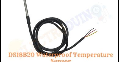
| DS18B20 Waterproof Temperature Sensor | 1 |
| 4 Channel Relay Module | 1 |
| Peltier Module ( TEC1-12705) | 2 |
| 16×2 LCD Display Module | 1 |
| 220 ohm Resistor (R1, R2, R3) | 3 |
| 4.7K ohm Resistor (R4) | 1 |
| 10K ohm Potentiometer (VR1) | 1 |
| Red LED (D1) | 1 |
| Green LED (D2) | 1 |
| DC Water Pump | 1 |
| 9v Power Supply | 1 |
| 12V/5A Power Supply | 1 |
| Slide Switch | 1 |
| PCB board | 1 |
| Connecting wires | As required in the circuit diagram |
Tools Required
| Tools Name | Quantity |
| Soldering Iron | 1 |
| Soldering wire | 1 |
| Soldering flux | 1 |
| Soldering stand | 1 |
| Multimeter | 1 |
| Desoldering pump | 1 |
| Wirecutter | 1 |
Software Required
|
|
Arduino IDE (Integrated Development Environment) |

Required Library
We need to add 2 libraries in Arduino IDE software. These are:
- DallasTemperature library
- OneWire library
*Click here to learn How to Download and install the DallasTemperature library and OneWire library
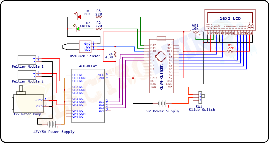
Circuit Diagram/Schematic of Aquarium Thermometer with Water Temperature Controller using DS18B20 Temperature Sensor and Arduino
Working Principle of Aquarium Thermometer with Water Temperature Controller
After connecting all the components according to the circuit diagram and uploading the Arduino programming, now our Aquarium Thermometer is ready to work. When we give the power supply to the thermometer the DS18B20 Temperature Sensor starts detecting the water temperature inside the Aquarium tank and generates Output values from the Data pin. The data pin of the temperature sensor is connected to the Digital Pin 10 of the Arduino. Arduino read these output values and calculates the water temperature in degrees Celsius by using the Arduino code. The Arduino displays the temperature values on LCD Display Module.
In this project, we are using two Peltier modules, Peltier modules have two surfaces, one surface having a warming effect and another surface having a cooling effect. The Peltier module-1 is used for heating up and the Peltier module- 2 is used for cooling down the water. Here we also used an aluminum water block, water is passing through the water block. The heating surface of the Peltier module-1 is mounting on one side of the aluminum water block and the cooling surface of the Peltier module-2 is mounting on another side of the aluminum water block. Nozzle one of the water block is connected to the outlet nozzle of the water pump and another nozzle is connected to the Aquarium tank. The input nozzle of the water pump is connected to the tank.
When the Arduino detects temperature values less than 23°C, it understood the water is cooling down. Then the Arduino grounded (LOW/0) the Input Pin 1 and Input Pin 3 of the Relay Module, which turn on the Peltier Module 1 and Water Pum. At this time, Arduino sends a command to the 16x2LCD Display module to print the message Peltier 1:ON, Water Pump: ON and Water Heating is in Process. The Red LED is glowing which indicates water temperature is going down under the normal temperature. In this condition, the Peltier module-1 stars heat up the Water Block. The water pump takes water from the aquarium tank and returns it to the tank by flowing through the water block. In this way Aquarium water temperature increases slowly and when the water temperature comes back to the normal temperature (25°C), then Arduino gives +5V (HIGH) to the Input Pin 1 and Input Pin 3 of the Relay Module, which turns OFF the Peltier Module 1 and Water Pum.
When the Arduino detects temperature values greater than 27°C, it understood the water is heating up. This time the Arduino grounded (LOW/0) the Input Pin 2 and Input Pin 3 of the Relay Module, which turn ON the Peltier Module 2 and Water Pum. At this time, Arduino sends a command to the 16x2LCD Display module to print the message “Peltier 2:ON, Water Pump: ON and Water Cooling is in Process”. The Red LED is glowing which indicates water temperature is crossed the normal temperature. In this condition, the Peltier module-2 starts cooling the Water Block. The water pump takes water from the aquarium tank and returns it to the tank by flowing through the water block. In this way, the Aquarium water temperature decreases slowly and when the water temperature comes back to the normal temperature (25°C), then Arduino gives +5V (HIGH) to the Input Pin 2 and Input Pin 3 of the Relay Module, which turns OFF the Peltier Module 1 and Water Pum.
Arduino Code for Aquarium Thermometer with Water Temperature Controller
/* Aquarium Thermometer with Water Temperature Controller
More info: https://www.electroduino.com */
//Include librarie for LCD Display
#include <LiquidCrystal.h>
// Include librarie for DS18B20 Temperature Sensor
#include <OneWire.h>
#include <DallasTemperature.h>
// Define LCD display pins
const int RS = A0, EN = A1, D4 = A2, D5 = A3, D6 = A4, D7 = A5;
LiquidCrystal lcd (RS, EN, D4, D5, D6, D7);
// Define which pin of the Arduino is connected to DS18B20 Temperature Sensor
#define ONE_WIRE_BUS 10
// Define the Arduino pin which is connected to the relay Module
const int RelayIn_1 = 9; // Relay-1 for Pelter Module 1
const int RelayIn_2 = 8; // Relay-2 for Pelter Module 2
const int RelayIn_3 = 7; // Relay-3 for Water Pump
// Define the Arduino pin which is connected to the Red LED
const int RED_LED_Pin = 12;
// Define the Arduino pin which is connected to the Green LED
const int GREEN_LED_Pin = 11;
// Create a new instance of the oneWire class to communicate with any OneWire device
OneWire oneWire(ONE_WIRE_BUS);
// Pass the oneWire reference to DallasTemperature library:
DallasTemperature sensors(&oneWire);

void setup()
  {
   // Begin serial communication at a baud rate of 9600
   Serial.begin(9600);
   // initialize LCD and set up the number of columns and rows
   lcd.begin(16, 2);
   // Start up the library:
   sensors.begin();
   // Set Arduino Pin as Output Pin
   pinMode(RelayIn_1, OUTPUT);
   pinMode(RelayIn_2, OUTPUT);
   pinMode(RelayIn_3, OUTPUT);
   pinMode(RED_LED_Pin, OUTPUT);
   pinMode(GREEN_LED_Pin, OUTPUT);

   // Print Beginning Message on LCD Display
   lcd.clear(); // Clear LCD Display
   lcd.setCursor(3,0);
   lcd.print("Welcome To");
   lcd.setCursor(2,1);
   lcd.print("ELECTRODUINO");
   delay(2000); // Wait 2 second

   lcd.clear(); // Clear LCD Display
   lcd.setCursor(0,0);
   lcd.print("Aquarium");
   lcd.setCursor(0,1);
   lcd.print("Thermometer");
   delay(2000);// Wait 2 second

   // Normally all relays are OFF
   digitalWrite (RelayIn_1,HIGH); // Peltier Module 1 OFF
   digitalWrite (RelayIn_2,HIGH); // Peltier Module 2 OFF
   digitalWrite (RelayIn_3,HIGH); // Water Pump OFF
  }

void loop()
  {
   // Send the command for all devices on the bus to perform a temperature conversion:
   sensors.requestTemperatures();
   // Fetch the temperature in degrees Celsius for device index:
   float tempC = sensors.getTempCByIndex(0); // the index 0 refers to the first device
   // Print the temperature in Celsius in the Serial Monitor:
   Serial.print("Temperature: ");
   Serial.print(tempC);
   Serial.print((char)223); // Print ° character
   Serial.print("C ");

   // When water temperature is less than 24°C. It means Water starts cooling down
   if(tempC < 24)
    {
     digitalWrite (RelayIn_1,LOW); // Peltier Module 1 ON
     digitalWrite (RelayIn_2,HIGH); // Peltier Module 2 OFF
     digitalWrite (RelayIn_3,LOW); // Water Pump ON
     digitalWrite (RED_LED_Pin, HIGH); // RED LED ON
     digitalWrite (GREEN_LED_Pin, LOW);// GREEN LED OFF

     lcd.clear(); // Clear LCD Display
     //Print the temperature in Celsius on LCD Display
     lcd.setCursor(0, 0); // Set the Message Position at the First Row
     lcd.print("Temp: ");
     lcd.print(tempC); // Print the Temperature in Celsius
     lcd.print((char)223); // Print ° character
     lcd.print("C");
     delay(1000); // Wait 1 second

     lcd.clear();  // Clear LCD Display
     //Print Peltier 1 & Pump ON Messge on LCD Display
     lcd.setCursor(0, 0); // Set the Message Position at the First Row
     lcd.print("Peltier 1 : ON");
     lcd.setCursor(0, 1); // Set the Message Position at the Second Row
     lcd.print("Water Pump : ON");
     delay(1000); // Wait 1 second

     lcd.clear();  // Clear LCD Display
     lcd.setCursor(0, 0); // Set the Message Position at the First Row
     lcd.print("Water heating is");
     lcd.setCursor(0, 1); // Set the Message Position at the Second Row
     lcd.print("in progress......");
     delay(1000); // Wait 1 second
    }

// When water temperature is greater than 24°C. It means Water starts heating up
   else if(tempC > 27)
    {
     digitalWrite (RelayIn_1,HIGH); // Peltier Module 1 OFF
     digitalWrite (RelayIn_2,LOW); // Peltier Module 2 ON
     digitalWrite (RelayIn_3,LOW); // Water Pump ON
     digitalWrite (RED_LED_Pin, HIGH); // RED LED ON
     digitalWrite (GREEN_LED_Pin, LOW);// GREEN LED OFF

     lcd.clear();  // Clear LCD Display
     //Print the temperature in Celsius on LCD Display
     lcd.setCursor(0, 0); // Set the Message Position at the First Row
     lcd.print("Temp: ");
     lcd.print(tempC); // Print the Temperature in Celsius
     lcd.print((char)223); // Print ° character
     lcd.print("C");
     delay(1000); // Wait 1 second

     lcd.clear(); // Clear LCD Display
     //Print Peltier 1 & Pump ON Messge on LCD Display
     lcd.setCursor(0, 0); // Set the Message Position at the First Row
     lcd.print("Peltier 2 : ON");
     lcd.setCursor(0, 1); // Set the Message Position at the Second Row
     lcd.print("Water Pump : ON");
     delay(1000); // Wait 1 second

     lcd.clear(); // Clear LCD Display
     lcd.setCursor(0, 0); // Set the Message Position at the First Row
     lcd.print("Water cooling is");
     lcd.setCursor(0, 1); // Set the Message Position at the Second Row
     lcd.print("in progress......");
     delay(1000); // Wait 1 second
    }

// When water temperature betweenn 24-27°C. It means Water temp is normal
   else
    {
     digitalWrite (RelayIn_1,HIGH); // Peltier Module 1 OFF
     digitalWrite (RelayIn_2,HIGH); // Peltier Module 2 OFF
     digitalWrite (RelayIn_3,HIGH); // Water Pump OFF
     digitalWrite (RED_LED_Pin, LOW); // RED LED OFF
     digitalWrite (GREEN_LED_Pin, HIGH);// GREEN LED ON

     lcd.clear(); // Clear LCD Display
     //Print the temperature in Celsius on LCD Display
     lcd.setCursor(0, 0); // Set the Message Position at the First Row
     lcd.print("Temp: ");
     lcd.print(tempC); // Print the Temperature in Celsius
     lcd.print((char)223); // Print ° character
     lcd.print("C");
     lcd.setCursor(0, 1); // Set the Message Position at the Second Row
     lcd.print("Good Temperature");
     delay(1000); // Wait 1 second
    }
  }