RFID Based Attendance System with Database Management using Arduino
Hello friends! Welcome back to ElectroDuino. This blog is based on RFID Based Attendance System with Database Management using Arduino. Here we will discuss the Introduction to RFID Based Attendance System with Database Management using Arduino, Project Concept, Block Diagram, Components Required, Circuit Diagram, Working Principle, and Arduino code.
What a PCB is actually for is that it makes sure that everything in a circuit is properly seated, wired, and protected from damage, especially during the PCB assembly process where components are mounted and connected. But this material decision has a huge impact on the way the PCB will behave in various conditions and in different places. What material is used for a PCB will affect the electrical conductivity, thermal stability, and mechanical stability, thus making it reliable and long-lasting.
Introduction
Generally, we have seen the paper-based Attendance system in our Schools, colleges, and offices where the teacher/lecturer/senior officers take attendance of the students/staff manually (by roll calls). But it takes almost 5 to 10 minutes and may sometimes cause errors.
Now technology is expanding day by day, where paper-based traditional attendance methods are shifting into electronic attendance systems. The new technologies are also being developed in the field of electronic attendance systems. There are different types of electronic attendance systems available in the market, the most popular systems are RFID-based, fingerprint/biometric, and face recognition attendance systems.
In this project tutorial, we will learn how to make an RFID based Attendance system using Arduino. Using this system students/staff can automatically mark their presence. In this system, students/staff have to issue a unique RFID card from their Schools/ colleges/ offices once, and Just by placing this unique RFID card on the reader module, they can easily mark their attendance.
Project Concept
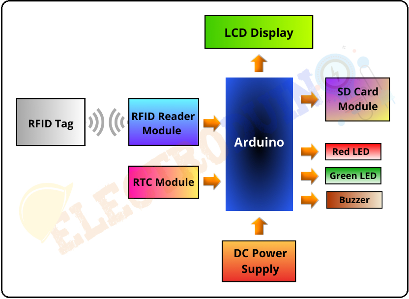
The primary goal of this project is to design a cost-effective and user-friendly attendance system using RFID technology. When a user places their RFID card near the RFID RC522 module, the system reads the card’s unique identifier. If a match is found, the system authenticates the user, allowing them access. Then the system sends timestamped attendance data to the Data Logger module, which saves the information on the connected microSD card. Attendance records, along with timestamps, are sent to the Micro SD Card module for secure and organized data storage. We can access the stored data on the microSD card for attendance tracking and analysis. The LCD display on the system provides real-time visual feedback, conveying information about successful card authentication and other relevant details.
Block Diagram of RFID Based Attendance System using Arduino
Components Required
| Components Name | Quantity |
| Arduino NANO | 1 |
| RC522 RFID Module | 1 |
| 13.56 MHz RFID Cards | 1 |
| DS1307 RTC Module | 1 |
| Micro SD Card Module |
1 |
| Micro SD Card 8GB/16GB |
1 |
| 16×2 LCD Display Module | 1 |
| 220 ohm Resistor (R1, R2, R3) | 3 |
| 10K ohm Potentiometer (VR1) | 1 |
| Red LED | 1 |
| Green LED | 1 |
| 5v Buzzer | 1 |
| 9v Power Supply | 1 |
| Rocker Switch | 1 |
| PCB board | 1 |
| Connecting wires | As required in the circuit diagram |
Tools Required
| Tools Name | Quantity |
| Soldering Iron | 1 |
| Soldering wire | 1 |
| Soldering flux | 1 |
| Soldering stand | 1 |
| Multimeter | 1 |
| Desoldering pump | 1 |
| Wirecutter | 1 |
Software Required

|
Arduino IDE (Integrated Development Environment) |
- Arduino Board: The microcontroller Arduino is the heart of the project, which is responsible for processing data and controlling other components. Here we have used an Arduino Nano board to make the system smaller and compact. You can use the other version of Arduino boards like Arduino UNO, Mega, etc.
- RC522 RFID Module: The RC522 RFID Reader Module is a cost-effective and widely used RFID module, which is responsible for wirelessly communicating with RFID cards or tags within its range. The RC522 reader operates at a frequency of 13.56 MHz, a common frequency for RFID applications. Here it is used for reading unique identifiers from the user’s RFID cards and facilitating user authentication.
- RFID Cards or Tags: RFID Cards/Tags are assigned to each user, these cards/tags serve as unique identifiers within the system.
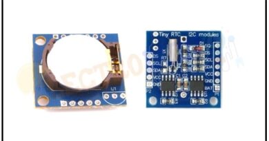
- DS1307 RTC Module: The DS1307 is a compact, low-power RTC (Real-Time Clock) module, designed to keep accurate track of time even in the absence of external power. The RTC Module provides accurate real-time clock data, ensuring precise timestamping of attendance records.
- Micro SD Card Module: The micro SD Card Module appears as a carrier for Micro SD cards. However, its significance lies in its ability to interface seamlessly with microcontrollers, facilitating the integration of expandable and portable data storage into a wide array of projects. Microcontrollers often have limited onboard storage. The Micro SD Card Module acts as an external storage solution, enabling the storage of program files, configuration data, and other resources. Here it is used as a Data Logger module, which enables the system to log and store attendance data for future analysis.
- DC Power Supply is used to supplies power to the Arduino and other connected modules.
- LEDs Indicate various system states or provide visual feedback for successful RFID card detection. Buzzer provides audible feedback for user authentication and system status.
“One standout feature that sets NextPCB.com apart is its DMF-free online Gerber viewer. This cutting-edge tool allows users to visualize their PCB designs with unprecedented clarity and detail. No more hassle with file conversions or compatibility issues – simply upload your Gerber files directly to the online viewer for a 360-degree view of your design. This feature is a testament to NextPCB.com’s commitment to user-friendly experiences and efficient workflows.“
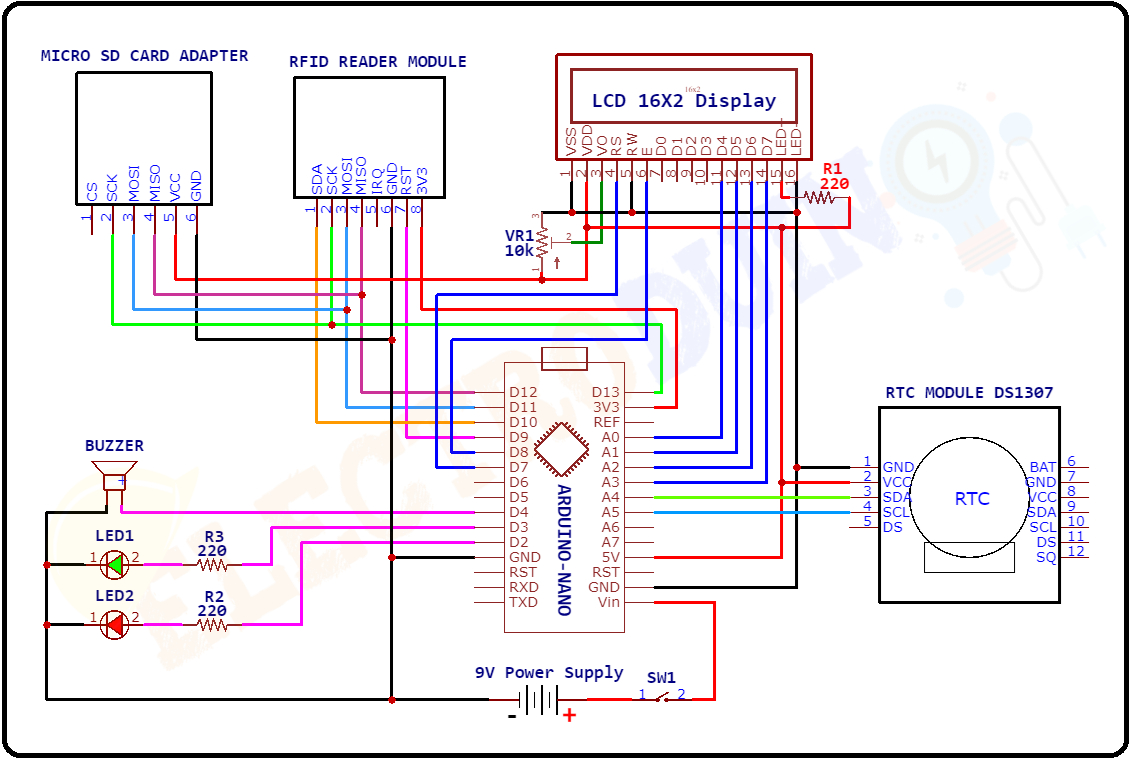
Circuit Diagram/Schematic of RFID Based Attendance System using Arduino
Working Principle of RFID Based Attendance System with Database Management using Arduino
Before using the system, each user is assigned a unique RFID card or tag. These RFID cards are initialized by associating them with specific user data, which could include personal information or an identification code. During the initialization phase, the RFID module is programmed to recognize and associate each card with specific user data. This is a one-time setup where the system learns to identify each user based on the unique RFID card assigned to them.
When a user approaches the RFID RC522 module and places their RFID card near it, the RFID module reads the unique identifier embedded in the card. This identifier is then cross-referenced with the pre-programmed data during the initialization phase. If a match is found, the system authenticates the user, allowing them access.
The Real-Time Clock (RTC) module is crucial for maintaining accurate timestamps. It provides the system with the current date and time information, ensuring that each attendance entry is associated with the correct time.
Once the RFID card is authenticated, the Arduino sends timestamped attendance data (like the user’s identification, the timestamp of the interaction, and some additional data) to the Micro SD Card module (Data Logger module). Then the Data Logger module writes this information to the connected microSD card to store the attendance details securely.
At the same time, the LCD provides real-time feedback on the authentication process. If the RFID card is recognized and the user is successfully authenticated, the LCD display module will display the LCD may display a welcome message along with the user’s name and a timestamp. Conversely, if there’s an issue with the RFID card or authentication process, an error message will displayed.
Parallely, LEDs and a Buzzer are used to provide clear indicators of system status.
- Green LED and single buzzer sound (Bip sound) signify the successful authentication.
- Red LED and multiple buzzer sounds (Bip-Bip-Bip… sound) indicate an unsuccessful attempt.
Attendance Management:
The stored data on the microSD card can be accessed for attendance tracking and analysis. System administrators or users can review the attendance records to monitor attendance patterns, identify trends, and generate attendance reports.
“In a game-changing move, NextPCB.com introduces Free PCB Assembly. Yes, you heard it right – free assembly for your prototypes. Now, you can experiment, innovate, and bring your ideas to life without worrying about assembly costs. It’s a bold step towards fostering creativity and breaking down barriers in the world of electronics.“
Arduino Code
#include <LiquidCrystal.h>
LiquidCrystal lcd(7, 8, A0, A1, A2, A3);

#include <MFRC522.h> // for the RFID
#include <SPI.h> // for the RFID and SD card module
#include <SD.h> // for the SD card
#include <RTClib.h> // for the RTC

// define pins for RFID
#define CS_RFID 10
#define RST_RFID 9
// define select pin for SD card module
#define CS_SD 4

// Create a file to store the data
File myFile;

// Instance of the class for RFID
MFRC522 rfid(CS_RFID, RST_RFID);

// Variable to hold the tag's UID
String uidString;

// Instance of the class for RTC
RTC_DS1307 rtc;

// Define check in time
const int checkInHour = 9;
const int checkInMinute = 5;

//Variable to hold user check in
int userCheckInHour;
int userCheckInMinute;

// Pins for LEDs and buzzer
const int redLED = 2;
const int greenLED = 3;
const int buzzer = 4;

void setup() {

  // Set LEDs and buzzer as outputs
  pinMode(redLED, OUTPUT);
  pinMode(greenLED, OUTPUT);
  pinMode(buzzer, OUTPUT);

  // Init Serial port
  Serial.begin(9600);
  lcd.begin(16,2);
  while(!Serial); // for Leonardo/Micro/Zero

  // Init SPI bus
  SPI.begin();
  // Init MFRC522
  rfid.PCD_Init();

  // Setup for the SD card
  Serial.print("Initializing SD card...");
  lcd.print("Initializing ");
  lcd.setCursor(0, 1);
  lcd.print("SD card...");
  delay(3000);
  lcd.clear();
  if(!SD.begin(CS_SD)) {
    Serial.println("initialization failed!");
    lcd.print("Initializing ");
    lcd.setCursor(0, 1);
    lcd.print("failed!");
    return;
  }
  Serial.println("initialization done.");
  lcd.print("Initialization ");
  lcd.setCursor(0, 1);
  lcd.print("Done...");

  // Setup for the RTC
  if(!rtc.begin()) {
    Serial.println("Couldn't find RTC");
    lcd.clear();
    lcd.print("Couldn't find RTC");
    while(1);
  }
  else {
    // following line sets the RTC to the date & time this sketch was compiled
    rtc.adjust(DateTime(F(__DATE__), F(__TIME__)));
  }
  if(!rtc.isrunning()) {
    Serial.println("RTC is NOT running!");
    lcd.clear();
    lcd.print("RTC Not Running!");
  }
}

void loop() {
  //look for new cards
  if(rfid.PICC_IsNewCardPresent()) {
    readRFID();
    logCard();
    verifyCheckIn();
  }
  delay(10);
}

void readRFID() {
  rfid.PICC_ReadCardSerial();
  lcd.clear();
  Serial.print("Tag UID: ");
  lcd.print("Tag UID: ");
  uidString = String(rfid.uid.uidByte[0]) + " " + String(rfid.uid.uidByte[1]) + " " +
    String(rfid.uid.uidByte[2]) + " " + String(rfid.uid.uidByte[3]);
  Serial.println(uidString);
  lcd.setCursor(0, 1);
  lcd.print(uidString);
  delay(2000);

  // Sound the buzzer when a card is read
  tone(buzzer, 2000);
  delay(200);
  noTone(buzzer);

  delay(200);
}

void logCard() {
  // Enables SD card chip select pin
  digitalWrite(CS_SD,LOW);

  // Open file
  myFile=SD.open("DATA.txt", FILE_WRITE);

  // If the file opened ok, write to it
  if (myFile) {
    Serial.println("File opened ok");
    lcd.clear();
    lcd.print("File opened ok");
    delay(2000);
    myFile.print(uidString);
    myFile.print(", ");

    // Save time on SD card
    DateTime now = rtc.now();
    myFile.print(now.year(), DEC);
    myFile.print('/');
    myFile.print(now.month(), DEC);
    myFile.print('/');
    myFile.print(now.day(), DEC);
    myFile.print(',');
    myFile.print(now.hour(), DEC);
    myFile.print(':');
    myFile.println(now.minute(), DEC);

    // Print time on Serial monitor
    Serial.print(now.year(), DEC);
    Serial.print('/');
    Serial.print(now.month(), DEC);
    Serial.print('/');
    Serial.print(now.day(), DEC);
    Serial.print(' ');
    Serial.print(now.hour(), DEC);
    Serial.print(':');
    Serial.println(now.minute(), DEC);
    Serial.println("sucessfully written on SD card");

    lcd.clear();
    lcd.print(now.year(), DEC);
    lcd.print(':');
    lcd.print(now.month(), DEC);
    lcd.print(':');
    lcd.print(now.day(), DEC);
    lcd.print(' ');
    lcd.setCursor(11, 0);
    lcd.print(now.hour(), DEC);
    lcd.print(':');
    lcd.print(now.minute(), DEC);
    lcd.setCursor(0, 1);
    lcd.print("Written on SD...");
    delay(2000);

    myFile.close();

    // Save check in time;
    userCheckInHour = now.hour();
    userCheckInMinute = now.minute();
  }
  else {

    Serial.println("error opening data.txt");
    lcd.clear();
    lcd.print("error opening data.txt");
  }
  // Disables SD card chip select pin
  digitalWrite(CS_SD,HIGH);
}

void verifyCheckIn(){
  if((userCheckInHour < checkInHour)||((userCheckInHour==checkInHour) && (userCheckInMinute <= checkInMinute))){
    digitalWrite(greenLED, HIGH);
    delay(2000);
    digitalWrite(greenLED,LOW);
    Serial.println("You're welcome!");
    lcd.clear();
    lcd.print("You're Welcome!");
  }
  else{
    digitalWrite(redLED, HIGH);
    delay(2000);
    digitalWrite(redLED,LOW);
    Serial.println("You are late...");
    lcd.clear();
    lcd.print("You are Late...");
    delay(3000);
    lcd.clear();
    lcd.print("Put RFID to Scan");

  }
}