Over Heat Detector with Auto Cooling System using Thermistor
Hello friends! Welcome back to ElectroDuino. This blog is based on Over Heat Detector with Auto Cooling System using Thermistor and 741 Op-Amp IC. Here we will discuss Introduction to Over Heat Detector with Auto Cooling, Project Concept, Block Diagram, Components Required, Circuit Diagram, and Working Principle.
Introduction
We all may have seen Computer/Laptop, it has a cooling fan inside. Normally this fan is off. When the computer’s motherboard starts to heat up, then the cooling fan automatically starts rotating and cools down the motherboard temperature. In this way, the cooling fan protects the components from overheating and damage. This type of system used in various devices. In this project, we will learn how this type of system work and how we can build it. This System is known as an Over Heat Detector with Auto Cooling System. It is also known as the Temperature control DC fan Circuit.
Project Concept
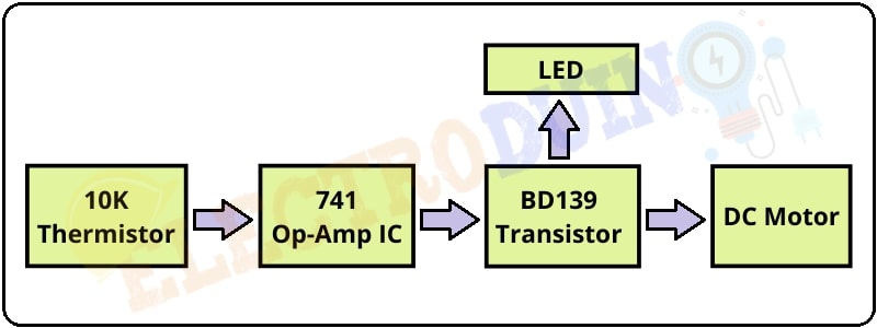
The Project working concept is very simple. This system continuously measures the temperature of a component, if the system detects that the component has started to overheat, then the system turns on the fan automatically. When the temperature comes to normal condition then the system turns off the fan automatically. We can build this system circuit easily. The key components of the Over Heat Detector with Auto Cooling System are 10k Thermistor, 741 Op-Amp IC, LED, BD139 Transistor, and DC fan. The 10k Thermistor works as a Heat Detector sensor. The 741 Op-Amp IC controls the whole system, it takes input from Thermistor, and generates output to control the transistor. The BD139 Transistor work as a switch, it controls the LED and DC fan. The LED used for overheating indicator. The DC fan is used to cool down the system from overheating.
Block Diagram of Over Heat Detector with Auto Cooling System
Components Required
| Components Name | Quantity |
| LM741 Op-Amp IC | 1 |
| BD139 Transistor | 1 |
| NTC 10k Thermistors (R2) | 1 |
| R1: 4.7 k ohm Resistors | 1 |
| R3 & R4: 1 k ohm Resistors | 1 |
| Potentiometer 10k ohm (RV1) | 1 |
| Red LED (D1) | 1 |
| 12v DC fan (Motor) | 1 |
| Slide Switch (SW1) | 1 |
| 12V Power Supply | 1 |
| PCB board | 1 |
| Connecting Wires | As required in the circuit diagram |
Tools Required
| Tools Name | Quantity |
| Soldering Iron | 1 |
| Soldering wire | 1 |
| Soldering flux | 1 |
| Soldering stand | 1 |
| Multimeter | 1 |
| Desoldering pump | 1 |
| Wirecutter | 1 |
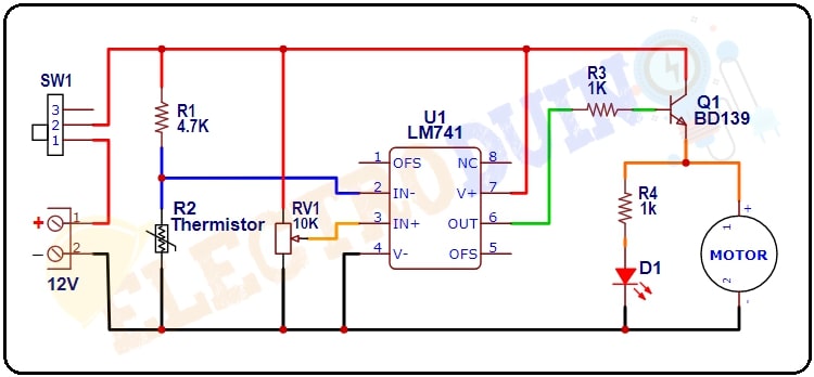
Circuit Diagram of Over Heat Detector with Auto Cooling System
Working Principle of Over Heat Detector with Auto Cooling System
In this Circuit, 4.7K resistor(R1) and NTC (Negative Temperature Co-efficient) 10k Thermistor (R2) are making a voltage divider circuit and the inverting terminal (IC PIN 2) of LM741 op-amp IC is connected between the R1 and R2. The 10k potentiometer’s (RV1) output pin is connected to the Non-inverting terminal (IC PIN 3) of LM741 op-amp IC. This potentiometer is used to set a reference voltage at the Non-inverting terminal.
When the Thermistor detects heat, its resistance starts to decreases, and the output of the voltage divider circuit is also decreased. This output goes to the inverting terminal (IC PIN 2). If this output voltage is less than the reference voltage at the Non-inverting terminal (IC PIN 3). Then the LM741 IC gives High output from the output Pin (IC pin 6). This High output voltage goes to the Base terminal of the BD139 Transistor through the 1k (R3). Now the transistor starts conducting and it gives operating voltage to the LED and DC which are connected to the Emitter Terminal of the transistor. Then the LED starts glowing and the fan starts rotating.
When the Thermistor detects low heat, again its resistance starts to increases, and the output of the voltage divider circuit is also increased. This time, the output voltage is greater than the reference voltage at the Non-inverting terminal (IC PIN 3). So, the LM741 IC output becomes LOW. This is not sufficient voltage at the base terminal to make the transistor conduct. So the LED and fan will automatically turn OFF.