

Interfacing IR Sensor with Arduino | IR Sensor Arduino Code
Hello friends! Welcome back to ElectroDuino. This blog is based on Interfacing IR Sensor with Arduino | Obstacle Detection using IR Sensor. In the previous blog post, we were discussing “IR Sensor Module | How IR Sensor Module Works“. Here we will discuss how to use IR sensor module with Arduino, Circuit diagram, Digital data read Arduino Code, obstacle detection using the IR sensor module, Circuit diagram, and Arduino Code.
Introduction
Interfacing IR Sensor with Arduino is a first step to understanding how to use an IR sensor in different projects. Here we will make a basic project, where the IR sensor detects an object and indicated by an LED. Using this project we will also learn how to connect this sensor to the Arduino and how the Arduino reads output data from the sensor using programming/code.
The project concept is very simple when an obstacle or object comes in front of the IR sensor, then the sensor gives an output to the Arduino, then the Arduino sent output voltage to turn on the LED. When the sensor doesn’t detect an obstacle or object, then the Arduino turns off the LED.
Components Required
| Components Name | Quantity |
| Arduino UNO (you can use other types of Arduino like Arduino Nano, MEGA, pro mini, etc) | 1 |
| IR Sensor Module | 1 |
| LED | 1 |
| 330ohm Resistor | 1 |
| Breadboard | 1 |
| Jumper wires | As required in the circuit diagram |
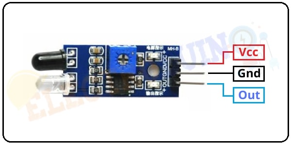
IR Sensor Module Pin Diagram
IR sensor module has 3 terminals these are OUT pin, GND pin, and VCC pin.
| For More Details: IR Sensor Module | How IR Sensor Module Works |
How to use IR Sensor Module with Arduino
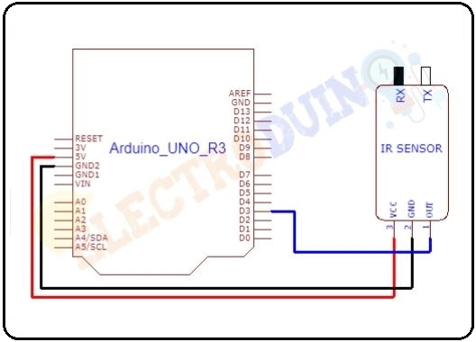
We need to connect the IR sensor with Arduino properly to read the output of the sensor. First of all, we connected the sensor Vcc pin to the Arduino 5v pin and the GND pin is connected to the Arduino ground (GND) pin, to activate the IR sensor module. Then connect the sensor output pin to one of the digital pin of Arduino to read the output value from the IR sensor module.
Arduino IR Sensor Circuit diagram
Circuit Wiring
| Components Pin | Arduino Pin |
| IR sensor Vcc Pin | + 5v Pin |
| IR sensor GND Pin | GND (ground) pin |
| IR sensor OUT Pin | Digital pin “D3” |
Read Digital Data from IR Sensor using Arduino
After connecting the sensor with Arduino, now time to write a few lines of code to read digital data from the sensor.
First of all, we need to define the Arduino Digital Pin which is connected to the sensor and takes a variable for named that pin. Here the variable’s name is “IRSensor”.
int IRSensor = 7;
Set pinMode of this Arduino pin as input for reading the output from the sensor.
pinMode (IRSensor, INPUT);
This line is used to start the serial communication between the Arduino and your computer through the USB connection. for print the sensor output data on the serial monitor. The value 9600 sets the data rate in bits per second for serial data transmission.
Serial.begin (9600);
Next comes the main line of this code, which is used to read digital data from the sensor. Here the digitalRead() function is used, which is used to read the logic state at the pin. This function read voltage at this pin is High (5V) or Low (0V) or, and represents the pin logic state 1 or 0 (or HIGH/LOW). Then store the read value in the “Sensordata” variable.
int Sensordata = digitalRead (IRSensor);
These links are used to print output values on your serial monitor window.
Serial.print("Sensor value:");
Serial.println(Sensordata);
Arduino Code for Reading Digital Output
int IRSensor = 7; // connect ir sensor to arduino pin 3

void setup()
 {
  pinMode (IRSensor, INPUT); // sensor pin INPUT
  Serial.begin (9600); // Starts the serial communication
 }

void loop()
 {
  //Define a variables for read the IRsensor
  int Sensordata = digitalRead (IRSensor);

  // Prints the output data on the Serial Monitor
  Serial.print("Sensor value:");
  Serial.println(Sensordata);
 }
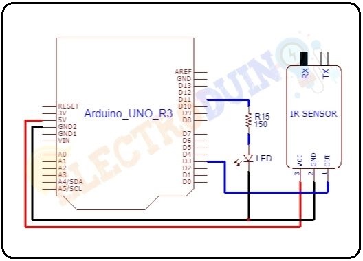
Obstacle Detection Circuit Diagram using IR Sensor Module and Arduino
Circuit Wiring
| Components Pin | Arduino Pin |
| IR sensor Vcc Pin | + 5v Pin |
| IR sensor GND Pin | GND (ground) pin |
| IR sensor OUT Pin | Digital pin “D3” |
| LED positive terminal | Digital pin “D13” through the 330 ohm resistor. |
| LED negative terminal | GND pin |
How the IR sensor module works as an obstacle detector
In this circuit, the sensor output pin is connected to the digital pin 3. The IR or obstacle sensor gives logic HIGH (1) as output when there is no obstacle in front of it, and it will give logic LOW (0) output when an obstacle is placed in front of it. We need to read these logical changes on the Arduino. The LED is an indicator which is connected to Arduino digital pin 11. Interfacing the IR sensor with Arduino works using simple Logic. That is If Arduino reads LOW data from the sensor output pin, LED should turn ON. Else if Arduino reads HIGH data from the sensor output pin, LED should turn OFF.
Obstacle Detection Arduino Code
int IRSensor = 3; // connect ir sensor to arduino pin 3
int LED = 11; // conect Led to arduino pin 13

void setup()
{
  pinMode (IRSensor, INPUT); // sensor pin INPUT
  pinMode (LED, OUTPUT); // Led pin OUTPUT
  Serial.begin (9600); //// Starts the serial communication
}

void loop()
{
  //Define a variables for read the IRsensor
  int Sensordata = digitalRead (IRSensor);

  // Prints the output data on the Serial Monitor
  Serial.print("Sensor value:");
  Serial.println(Sensordata);

  if (Sensordata == 0)  //Check the sensor output
  {
    digitalWrite(LED, HIGH); // LED High
    }

  else
  {
    digitalWrite(LED, LOW); // LED LOW
  }

}
Code Analysis
| Code Line | Description |
int IRSensor = 3; |
it is declared your IR sensor out pin connected to Arduino pin “D3” and named as IRSensor. |
int LED = 11; |
it is declared your LED pin connected to Arduino pin “D11” and named as LED. |
pinMode (IRSensor, INPUT); |
initialize Arduino digital pin 3, as an INPUT. That will read the output from your IR Sensor. |
pinMode (LED, OUTPUT); |
initialize Arduino digital pin 11, as an OUTPUT. That will provide input voltage to the LED. |
Serial.begin (9600); |
this function starts serial communication, at 9600 bits of data per second, between your board and your computer with the line. |
int Sensordata = digitalRead(IRSensor); |
The digitalRead() function is to read the raw digital value read from the sensor and store this value in the variable Sensor data. |
Serial.print("Sensor value:"); Serial.println(Sensordata); |
You need to print the sensor value on your serial monitor window using this command. |
|
|
If Arduino reads “LOW or 0″ from the IR sensor then Arduino provides digital value to turn ON the LED. |
|
|
Else Arduino reads “HIGH or 1″ from the IR sensor then Arduino does not provide digital value to LED and turn OFF the LED. |
Output
If you put an obstacle or object in front of the IR sensor, the LED is turn ON. When you remove the obstacle in front of it, LED is turn OFF.


