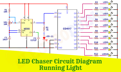
LED Chaser Circuit Diagram | Running Light
Hello friends! Welcome back to ElectroDuino. This blog is based on how to make LED Chaser Circuit Diagram | Running Light using IC 555 and CD 4017. Here we will discuss the Introduction to the LED Chaser Circuit, Project Concept, Block Diagram, Components Required, Circuit Diagram, and Working Principle.
Introduction
What is LED Chaser Circuit: The LED Chaser Circuit is an electronics circuit where the LEDs lights are glowing one by one for a period of time and the cycle repeats giving the running light appearance. You probably saw the various types of adornment lighting patterns in fair, some of the LED Light patterns are built based on the LED Chaser Circuit. Basically, a Simple LED Chaser Circuit is made of 555 Timer IC and CD4017 counter IC. Using this circuit we can build different types of home decoration products and Running LED light displays.
Project Concept of LED Chaser Circuit | Running Light
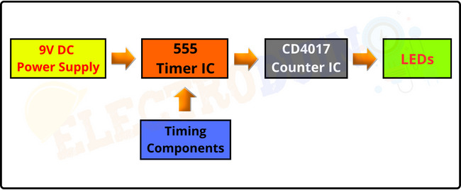
The LED Chaser Circuit Diagram | Running Light circuit project Concept and construction is very easy, few key components are needed to build it. The key components are NE555 timer IC, Potentiometer, Resistor, Capacitor, CD4017 Counter IC, and LEDs. Here we will configure the 555 timer IC as a frequency generator. It generates adjustable output frequency from its Output pin. The Potentiometer, Resistor, and Capacitor are act as the timing components, these are connected to the 555 timer IC. By adjusting the Potentiometer we can change the output frequency of the 555 IC. The output of the timer IC is given to the CD4017 Counter IC as input. The output frequency changes the output state of the counter IC. 10 LEDs are connected to the output pins of the counter IC, so the LEDs will be glowing one by one, and the Running light appearance in a sequenced manner.
Block Diagram of LED Chaser Circuit | Running Light
Components Required
| Components Name | Quantity |
| NE555 Timer IC | 1 |
| CD4017 Counter IC | 1 |
| 10K ohm Resistor (R1) | 1 |
| 1K ohm Resistor (R2) | 1 |
| 150 ohm Resistor (R3 – R12) |
10 |
| 10uf/16v Electrolytic Capacitor (C1) | 1 |
| 0.01uf Ceramic Capacitor (C2) | 1 |
| 10K ohm Potentiometer (VR1) | 1 |
| LED | 11 |
| 9v Power Supply | 1 |
| Slide Switch | 1 |
| PCB board | 1 |
| Connecting wires | As required in the circuit diagram |
Tools Required
| Tools Name | Quantity |
| Soldering Iron | 1 |
| Soldering wire | 1 |
| Soldering flux | 1 |
| Soldering stand | 1 |
| Multimeter | 1 |
| Desoldering pump | 1 |
| Wirecutter | 1 |
Circuit Diagram of LED Chaser Circuit | Running Light

Working Principle of LED Chaser Circuit
The main part of this LED chaser circuit diagram is the most popular timer IC NE555 which generates some variable frequency. The 555 timer IC can be configured in some different modes like Astable, Monostable, and Bistable, in this project we configured it as an Astable multivibrator in which both the stages of the signal are unstable. Sometimes this configuration is also known as a frequency generator.
Resistors R1, Potentiometer VR1, and capacitor C1 act as the timing components and we can change the output frequency cycle of 555 timer IC by adjusting the Potentiometer VR1. By changing the output frequency we can change the switching speed of the LEDs. The output pulses are available from the output pin 3 of 555 IC.
555 timer IC output frequency formula:
The charge time (HIGH output) formula is given by:
T1 = 0.693 (R1 +VR) C1
The discharge time (LOW output) formula is given by:
T2 = 0.693 (R2) C1
So, the total Time Period (T) is given by:
T = T1 + T2 = 0.693 (R1 + 2VR) C1
The frequency (F) of oscillation is:
F= 1/T
F=1.44/(R1+2VR)C1
These output pulses are given to the Clock pin (pin 14) of the counter IC CD4017 which trigger this counter IC to change its output state. 10 LEDs are connected to the output pin (Q0-Q9 pin) of the counter IC through 150 ohm resistor. The MR pin (pin 15) and the enable or clock inhibit pin (pin 13) of the CD4017 IC is directly connected with the ground. So, after connecting the power supply the circuit gives a blinking effect in a sequential manner. It means, when LED-1 turns on, this time other LEDs are turned off, then LED-2 will turn on and the other LEDs are turned off. In this way, The LED glows one by one and this cycle repeats giving the running light appearance.